System Logic
GARD 8000 SYS RFL Electronics
March 26, 2008 8-21 973.334.3100
8.6 LOGIC DESIGN RESERVED I/O
The following section describes the input and output bits that are reserved for specific operations in the
GARD8000 logic design.
8.6.1 HMI BIT ASSIGNMENT
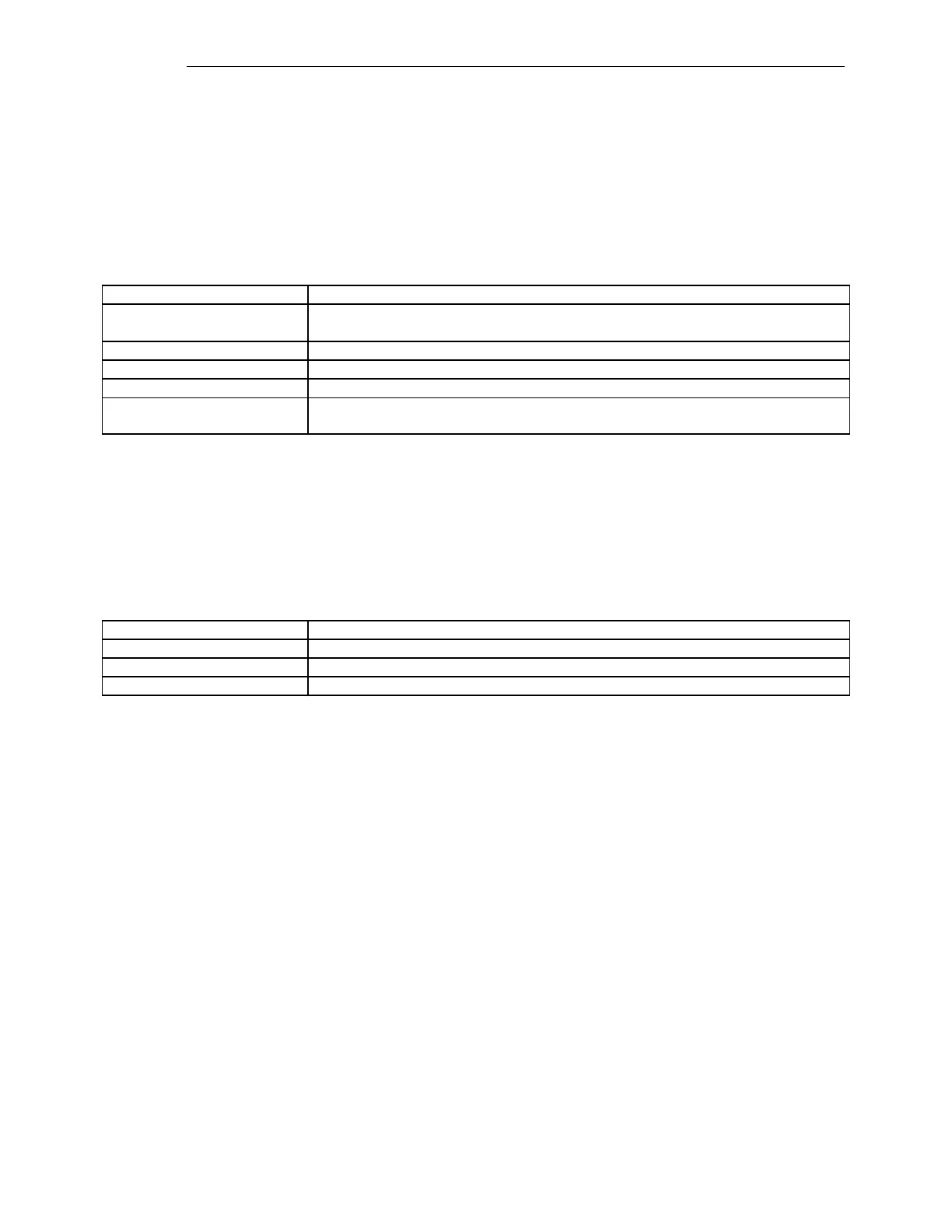
Table 8-15. HMI Bit Assignment
Reserved by the system to allow the CPU of the Controller Module to force SOE
records.
Driven by the Front Panel pushbutton.
Driven by the Logic Options settings as defined by the Options Settings web page.
Used for alarms as defined by the Alarms Configuration web page.
Current states appear in the Edit HMI Labels web page and can have user defined
labels assigned.
Note that the current Edit HMI Labels web page has HMIIN0, HMIIN1 and HMIOUT0 as reserved.
The next software revision will update the web page to reflect the above table.
8.6.2 SOE TRIGGERS BIT ASSIGNMENT
Table 8-16. SOE Triggers Bit Assignment
These bits are available to drive SOE events.
*Used to prevent excess SOE events in Remote PLC Checkback.
*Note that these bits can be assigned to general SOE use as long as the following rules are observed.
1. Certain SOE triggers are predefined as ON/OFF Block Received bits. SOE’s are
recorded every time one of these becomes active. Logic must be included on the local
and remote Chassis to block this input if a matching PLC Test in Progress is active.
TRIG184 = Block Received PLC unit 1
TRIG185 = Block Received PLC unit 2
TRIG186 = Block Received PLC unit 3
TRIG187 = Block Received PLC unit 4
2. Certain SOE triggers are predefined as Checkback Test in Progress bits. The activation
of one of these triggers will cause an SOE to be stored. In addition, when one of these
triggers becomes active, any SOE trigger caused by a matching Received Block
Trigger, that was received in the last 4-5 seconds must be deleted.