GARD Metering Module
GARD 8000 SYS RFL Electronics
April 1, 2007 15-1 973.334.3100
SECTION 15. GARD METERING MODULE
15.1 OVERVIEW
The Metering Module measures/calculates floating point values and sends them via a control bus to a
Status Webpage. Each of the measured values has a settable lower and upper threshold. For all of the
thresholds, multiple units can be set with different pickup values and time delays. The following 32 bit
values are measured.
Positive sequence current
Negative sequence current
Positive sequence voltage
Negative sequence voltage
Rate of Change of frequency
The result of these threshold measurements are web page status indications and logic bit outputs that
can be sent via the TPS function. The analog values can be displayed on a web page and eventually
combined with other values mathematically and sent via DNP* over an IP link to a control center.
*DNP is a serial communications protocol used by utility companies. DNP provides the rules for
substation computers and master station computers to communicate data and control commands. See
the following section (Section 16) for details on configuring the GARD for DNP3.
The following pages provide information on setting-up and using the GARD Metering Module.
15.2 TERMINAL BLOCK CONNECTIONS
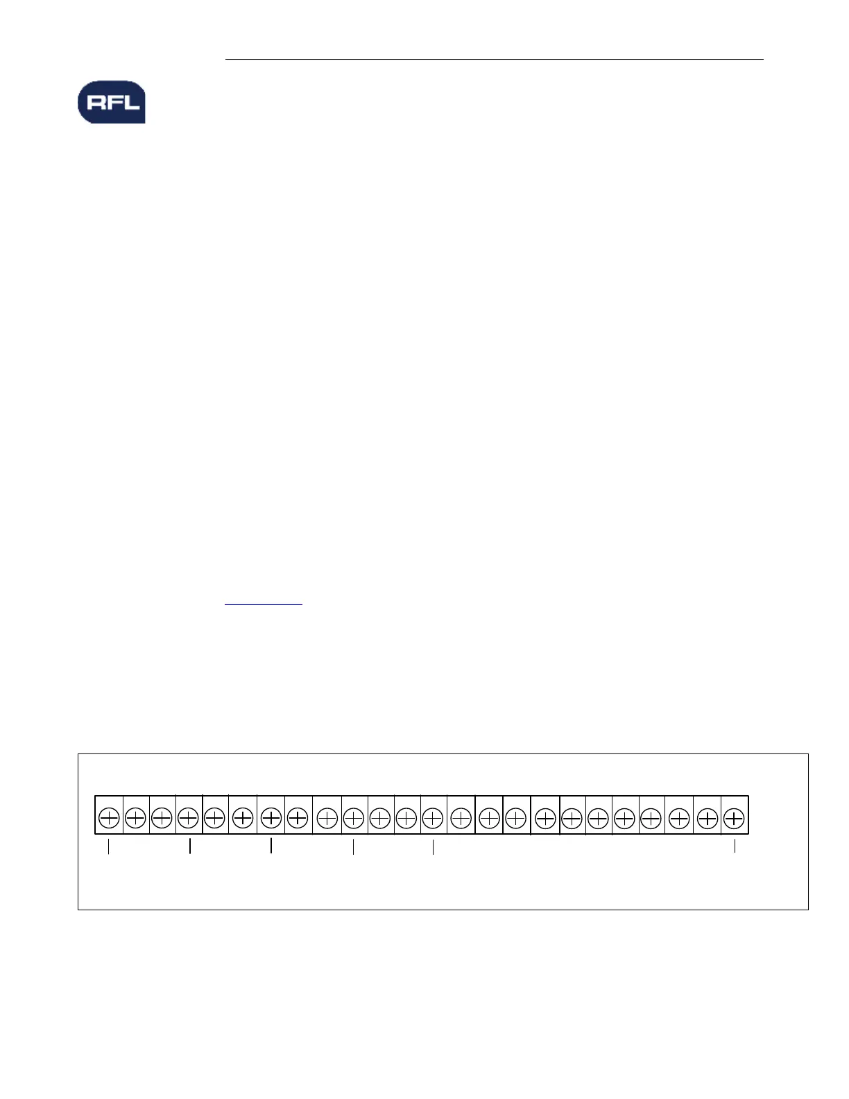
Connections are made to the Metering Module on the rear of the GARD chassis as shown below. The
terminal assignments are the same for the 3U and 6U chassis.
12346 58910 714 13 12 1118 17 16 1521 20 19222324
Chassis
GND
VA+
VC+
VC-
VA-
VB+
VB-
Chassis
GND
IA+IA-IB+
Chassis
GND
IB-
IC+
Chassis
GND
IC-
Chassis
GND
Chassis
GND
Figure 15-1. Metering Module Terminal Block Connections


 To Next Page