Applications
GARD 8000 SYS RFL Electronics
February 14, 2011 2-8 973.334.3100
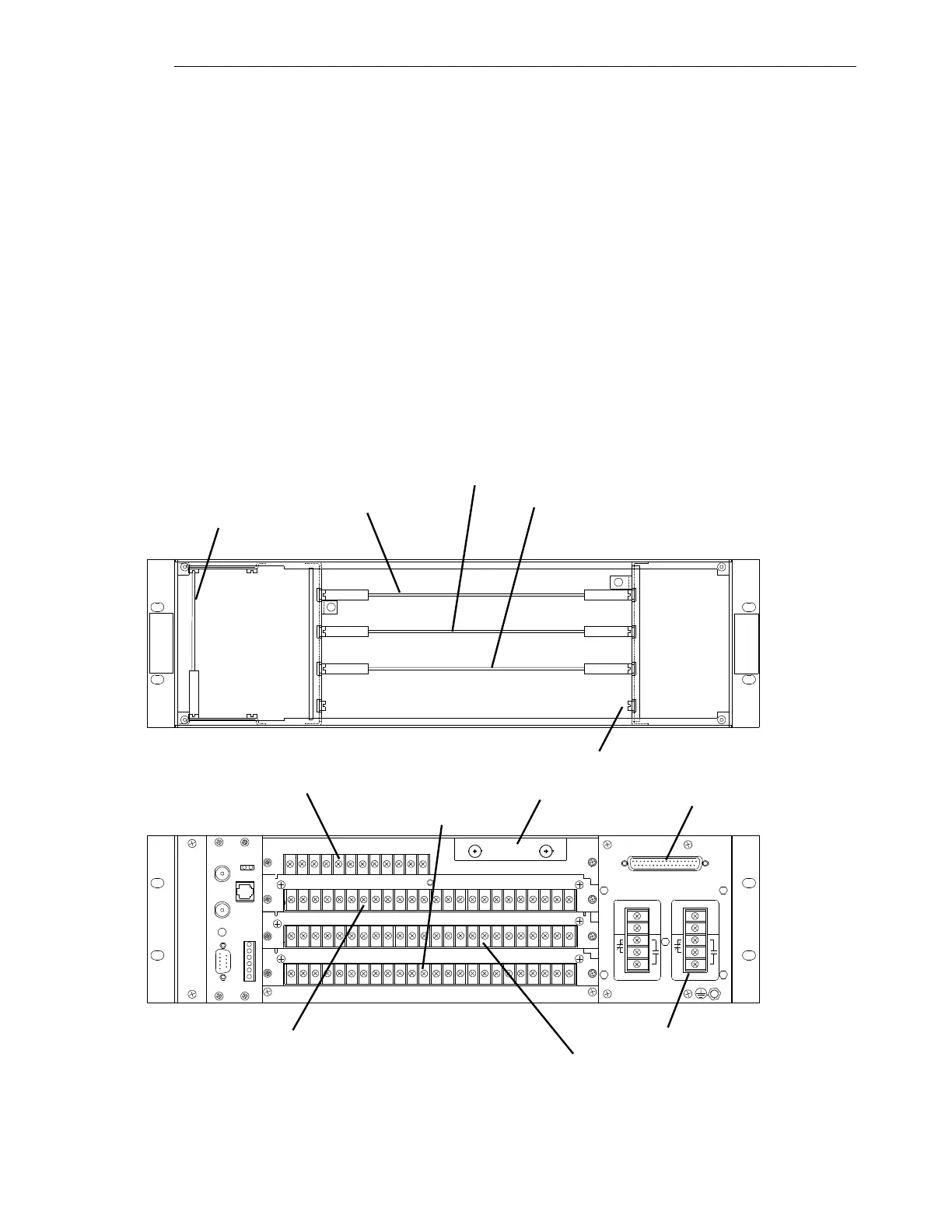
2.3.3 GARD 8000 HARDWARE CONFIGURATION
A GARD 8000 System can be built up with Functional Modules as required for a specific application.
The following example describes a factory default configuration of a 3U chassis consisting of the
following modules:
Single Power Supply
Single Main Controller
Display with TPS Module
Digital Interface (RS449/X.21/V.35) comms port on the rear of the PS module (included in
Base System)
C37.94 comms module in rear Slot 1
Distance Relay module set (One module in front Slot 3, and one module in rear Slot 3)
12 input module in rear Slot 2
12 output module (6 solid state and 6 relay out) in rear Slot 4
+
-
+
-
3U Chassis Front View
3U Chassis Rear View
Display with TPS (Slot 1)
Distance Relay (Slot 3)
Single Main Controller (Slot 2)
RS-449 Digital Interface
Single Power Supply
C37.94 Comms Module (Slot 1)
12 Input (Slot 2)
Single Power Supply
Unused I/O (Slot 1)
Distance Relay (Slot 3)
12 Output (Slot 4)
Unused (Slot 4)
Figure 2-5. Front and Rear of 3U Chassis