Installation and Commissioning
GARD 8000 SYS RFL Electronics
November 28, 2017 4-8 973.334.3100
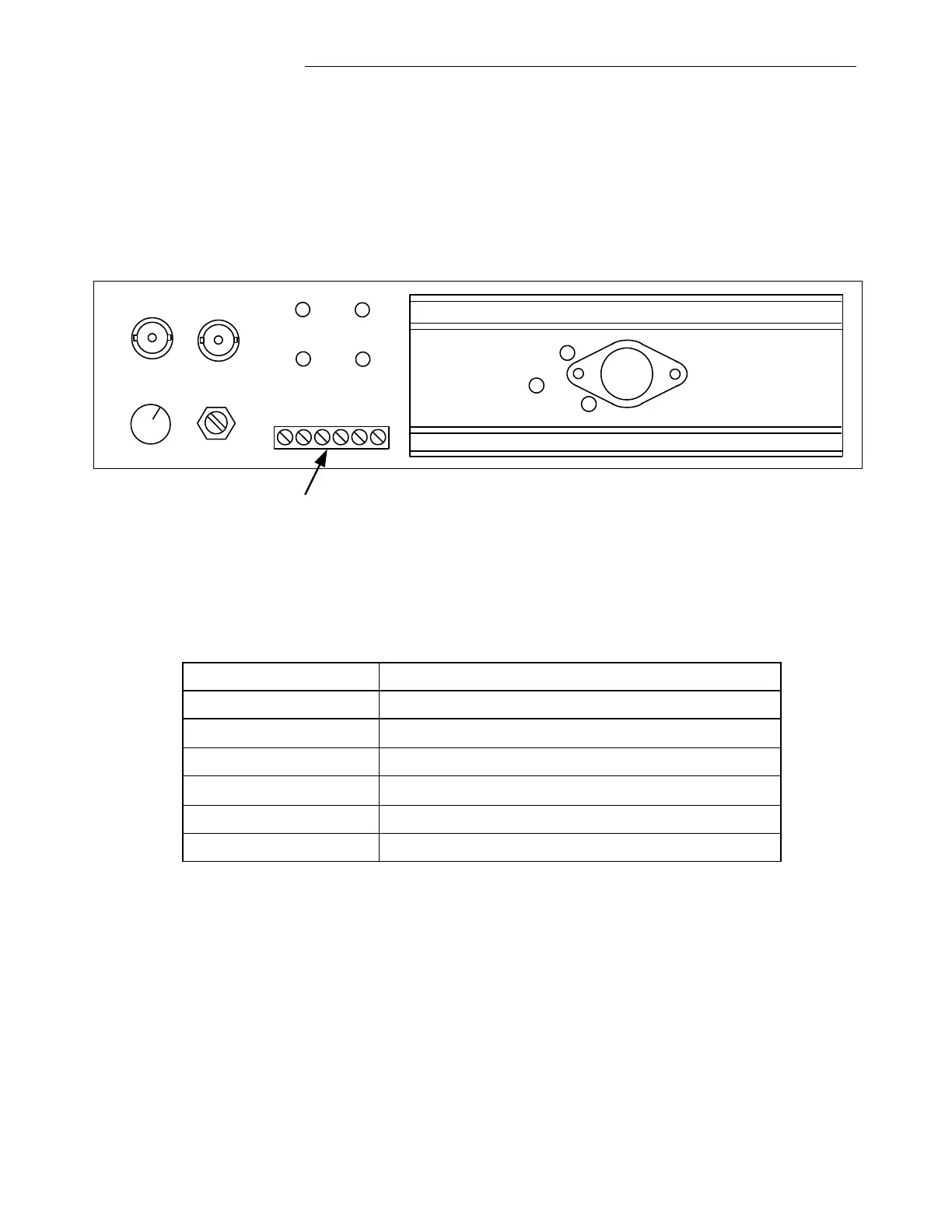
If your GARD 8000 is equipped with PLC Modules, connections must be made between the Tx and Rx
connectors on the PLC Analog module rear panel, and the Power Line Interface. Type BNC connectors
are used for these connections at the GARD 8000 end of the connection.
When using PLC Modules in a 3U chassis, the GARD 8000 power supply is adequate to power the full
chassis including the 10W amplifier; however, some 6U chassis installations may require an external
+/-15Vdc power supply. This connection is made to the plug-in auxiliary connector (TP1) at the rear of
the PLC Analog chassis as shown below.
COARSE FINE
RX TX
+15
-15
GND
CLI
GND
TB1
Figure 4-3. Location of TB1
Terminal assignments for TB1 are shown below.
Table 4-1. TB1 Terminal Assignments
+15Vdc from external supply when required
-15Vdc from external supply when required
* To observe the Carrier Level, connect an external meter to TB1 pins 4 and 6. Then refer to
Section 10.7 for additional information.
4.5.7 COMMS MODULES MATING CONNECTORS
Comms Modules mating connectors are given in Table 4-2.