Power Line Carrier
GARD 8000 SYS RFL Electronics
April 23, 2015 10-41 973.334.3100
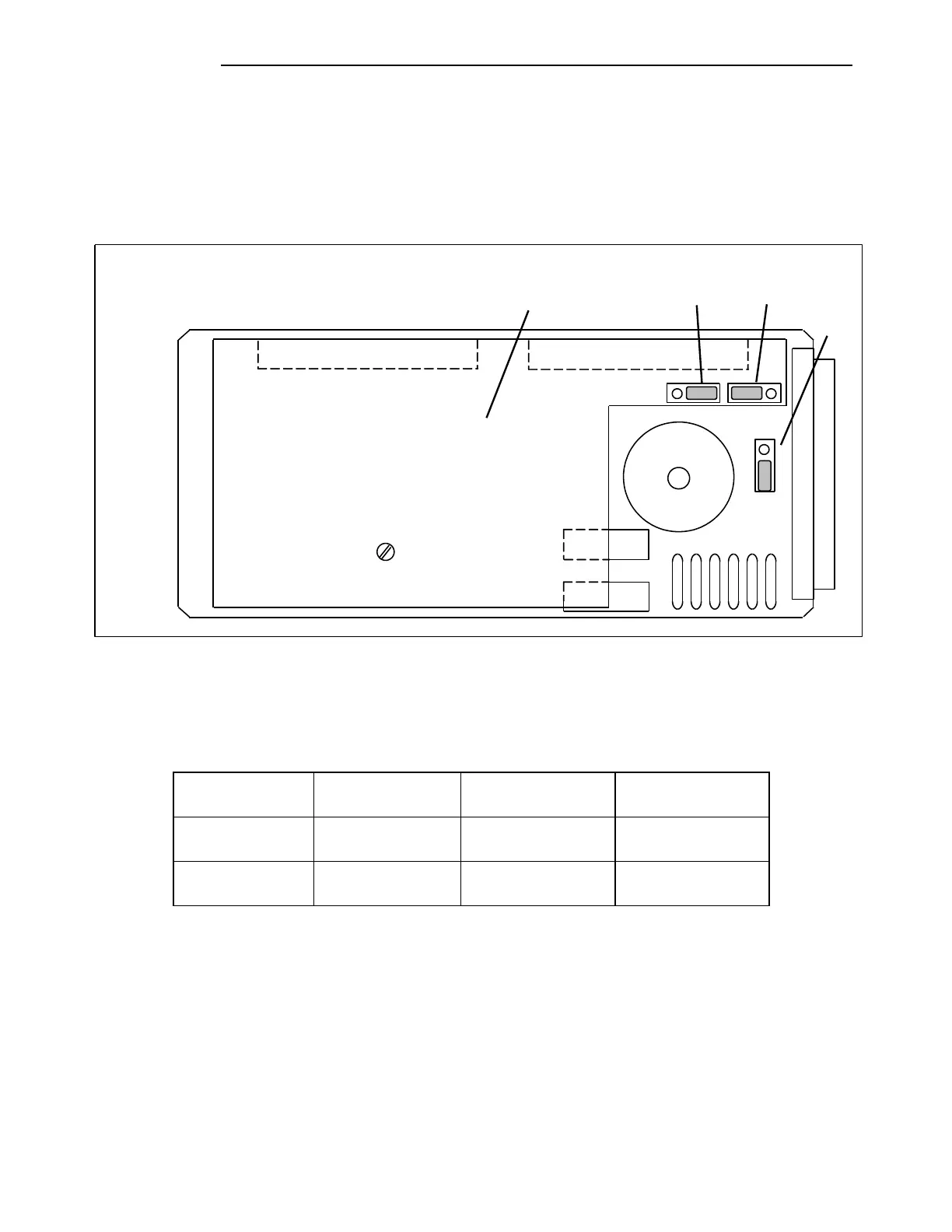
10.8.13.3 BALANCE BOARD JUMPER SETTINGS
The Balance Board has three jumpers J2, J3 and J4 that must be set for proper system operation. The
jumper settings select either 50W or 100W operation and must be set in accordance with the table
below. The jumper locations are shown below and are accessible only when the Balance Board is
removed from the chassis.
T1
K1
K2
HEAT SINK
R3
R4
J2
J3
J4
1
2
3
3
2
1
1
2
3
Figure 10-29. Location of jumpers on the Balance Board
Table 10-19. Setting Jumpers on the Balance Board