Applications
GARD 8000 SYS RFL Electronics
May 1, 2013 2-12 973.334.3100
The HMI processor provides all user communication interfaces. The main user interface is the resident
web server, accessed by a web browser on a PC via the rear or front Ethernet interface or via the front
RS-232 serial port. The HMI processor also handles the front display and any optional network
interfaces (DNP 3.0, Modbus or IEC61850).
In addition to user interfacing, the HMI processor communicates with and configures all of the other
modules in the chassis. The settings provided by the user are stored and forwarded to the functional
modules at power up. The HMI processor also retrieves status information from the modules and
presents it to the user.
2.4.3.2 LOGIC PROCESSOR
The Logic Processor functions as the brain of the system. It provides teleprotection system logic and
customized logic for coordination of all functional modules and mapping of inputs and outputs.
All functional units provide a set of binary inputs to the logic processor where they will be executed
according to the logic diagram.
2.4.4 GPS RECEIVER OPTION
When the GPS built-in receiver is included, it resides as a piggy-back module on the System I/O
Module. When the GPS receiver is present, the rear IRIG-B and 1-PPS (one pulse per second) ports on
the rear System I/O board convert from inputs to outputs. They are thus available for time
synchronization of external devices.
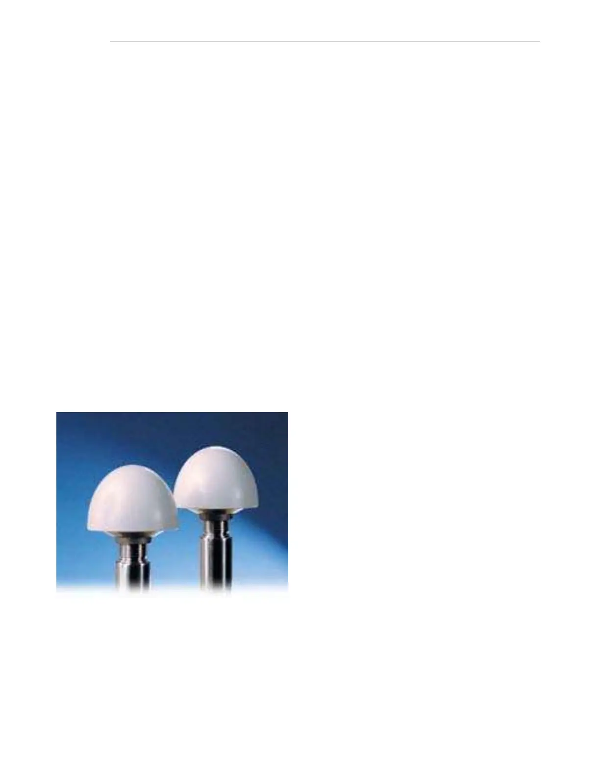
The GPS receiver has to be connected to an externally mounted antenna, provided as an accessory.
Figure 2-8. Antenna
2.4.5 METERING MODULE OPTION