Module Descriptions
GARD 8000 SYS RFL Electronics
April 23, 2015 6-32 973.334.3100
The function of the Discrete I/O Base module (500800) is to hold two I/O modules. The two I/O
modules plug onto the Discrete I/O Base using an array of connector pins on the Discrete I/O base
which plug into mating connectors on the I/O modules. The location of the I/O modules on the
Discrete I/O base is shown in Figure 6-18.
There are three types of I/O modules that can be mounted on the Discrete I/O Base as follows:
Input Unit
SS Output Unit
Relay Output Unit
6.7.1 INPUT UNIT
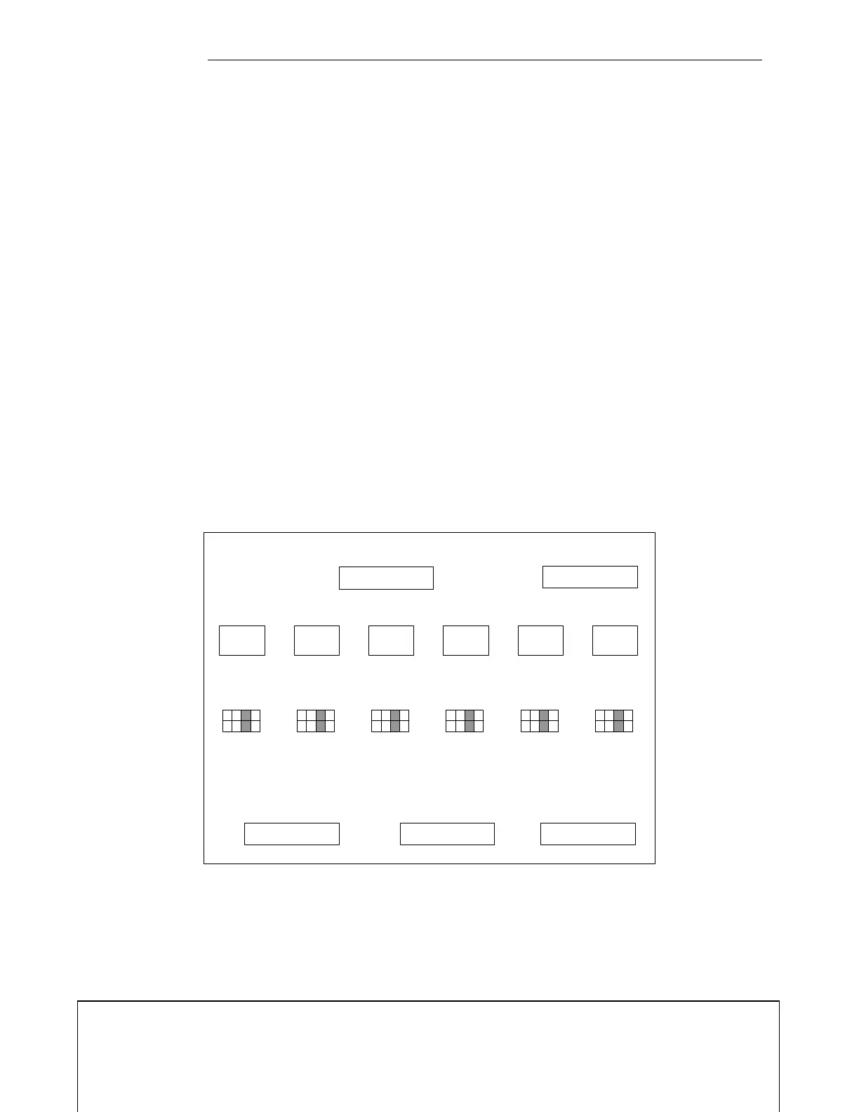
The Input Unit (500805) has six inputs, which can accommodate 24Vdc, 48Vdc, 125Vdc or 250Vdc.
These voltages are selectable by a user via jumpers (J12, J11, J10, J9, J8 and J7) on the Input Unit.
Figure 6-17 shows the location of these jumpers.
A voltage is selected by inserting a jumper. The Input Unit in Figure 6-17. shows 48V selected for J7
through J12. When the input unit is installed in a Discrete I/O Base module, J12 on the Input Unit
corresponds to terminals 23 and 24 on the Discrete I/O Base module, J11 on the Input Unit
corresponds to terminals 22 and 21 on the Discrete I/O Base module, and so forth. The same
correlation exists when the unit is plugged onto a Comms I/O Base module. This is shown pictorially
in Figure 6-19.
GARD 8000 INPUT UNIT
J12
J11
J10 J9
J8
J7
24V
24V
24V
24V
24V
24V
48V
48V
48V
48V
48V
48V
125V
125V
125V
125V
125V
125V
250V
250V
250V
250V
250V
250V
Figure 6-17. Component side of Input Unit (500805)
6.7.1.1 REDUNDANT INPUT UNIT
The Redundant Input Unit (500805-1) is used to provide redundant protection of the opto-isolators.
The configuration and jumper settings are identical to the Input Unit.