Tests and Diagnostics
GARD 8000 SYS RFL Electronics
February 14, 2011 11-32 973.334.3100
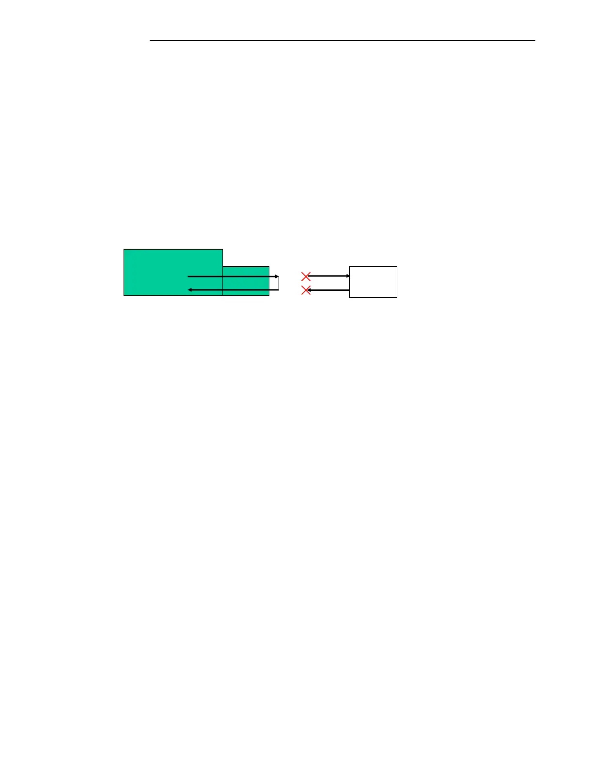
External Loop-Back:
The fiber optic interface can be looped back using a fiber optic patch cord. This will not require
activating any of the Loop-Back modes on the test page.
Set the Fiber Optic interface to internal timing on the settings page.
Label the existing fiber optic cables as the transmitter and receiver then remove the
fibers from the GARD 8000 chassis and install protective covers over the ends of the
fibers.
Install the fiber optic patch cord between the TX and RX connectors on the Fiber Optic
interface.
Set the devices mapped to the interface to be tested, TPS channels or Functional
modules, TX and RX addresses to the same value.
Figure 11-17. Manual Loopback
Read only status information:
Frame Lock:
Indicates that the framer has properly locked on the received data’s framing bit.
Transmit Activity:
Indicates the presence of outgoing data on the communications bus.
Receive Activity:
Indicates the presence of incoming data on the communications bus.
PLL Lock:
Indicates a valid Phase Lock Loop, received data and received clock are locked together and
not drifting with respect to each other. Failure to properly lock could result in bit errors and
communication failure.
Line Rate:
Provides the line rate, or bandwidth, of the Fiber Optic interface module to the external
communications equipment.
Interface Clock Polarity:
Give the programmed clock polarity for the interface. The transmit and receive clocks can be
set for either “Normal” or “Inverted".
Terminal