Installation and Commissioning
GARD 8000 SYS RFL Electronics
November 28, 2017 4-49 973.334.3100
The user should confirm that the commissioning value is approximately correct. This ensures
that the expected RX signal is being received when the commissioning took place. Bad cables,
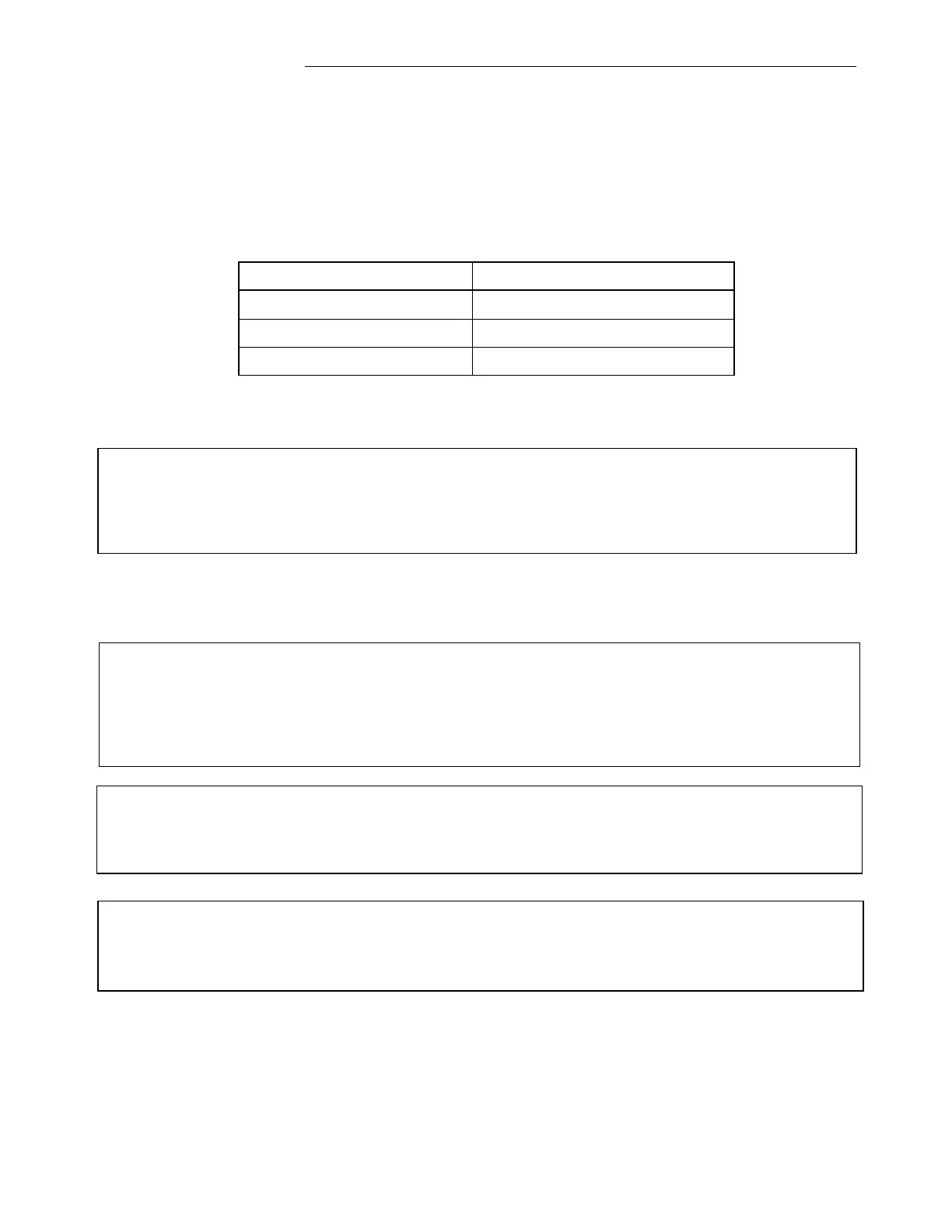
improper settings etc. can interfere with commissioning. The RX attenuation reading in the test
page after commissioning gives an indication of the received signal level. If the table on the next
page indicates a significantly lower RX level than expected, cable connections and signal levels
should be verified and commissioning re-run.
Incoming Signal Level (dBm)
e. Record the actual reading with FSVM ____________________
CAUTION
If your GARD 8000 has more than two PLC Digital Modules installed, remove the additional PLC
Modules from the front of the unit when upgrading to new PLC software. You can only upgrade a
PLC Module with ONE additional PLC Module installed.
4.6.3.4 RFL GARD 8000 COMMISSIONING TEST PROCEDURES FOR THE 9508
RF CHASSIS (50 AND 100W SYSTEMS)
WARNING!
The 9508 RF Chassis (50 watt amplifier) should never run without a 50 ohm load. To prevent this
remove input connector J5 prior to removing the output connector J2 on the power amplifier
circuit board.
CAUTION
Transmitter alignment should be performed at low power to avoid accidental damage to high power
amplifiers and power supplies.
CAUTION
The Power Amplifier will shut down if not properly terminated; conduct Line Tuning Procedures at
reduced power levels (FSK – Guard, ON/OFF – Reserve Key).
4.6.3.4.1 TRANSMITTER FUNCTIONAL TEST
The 9508 RF chassis (high power amplifier chassis) was factory configured according to strapping
charts on the equipment drawings provided with the equipment. No changes should be required unless
frequencies or system configuration is changed. See section 10.8 of this manual or the factory system
drawings provided with this equipment for proper jumper setting on all modules in the RF section. See