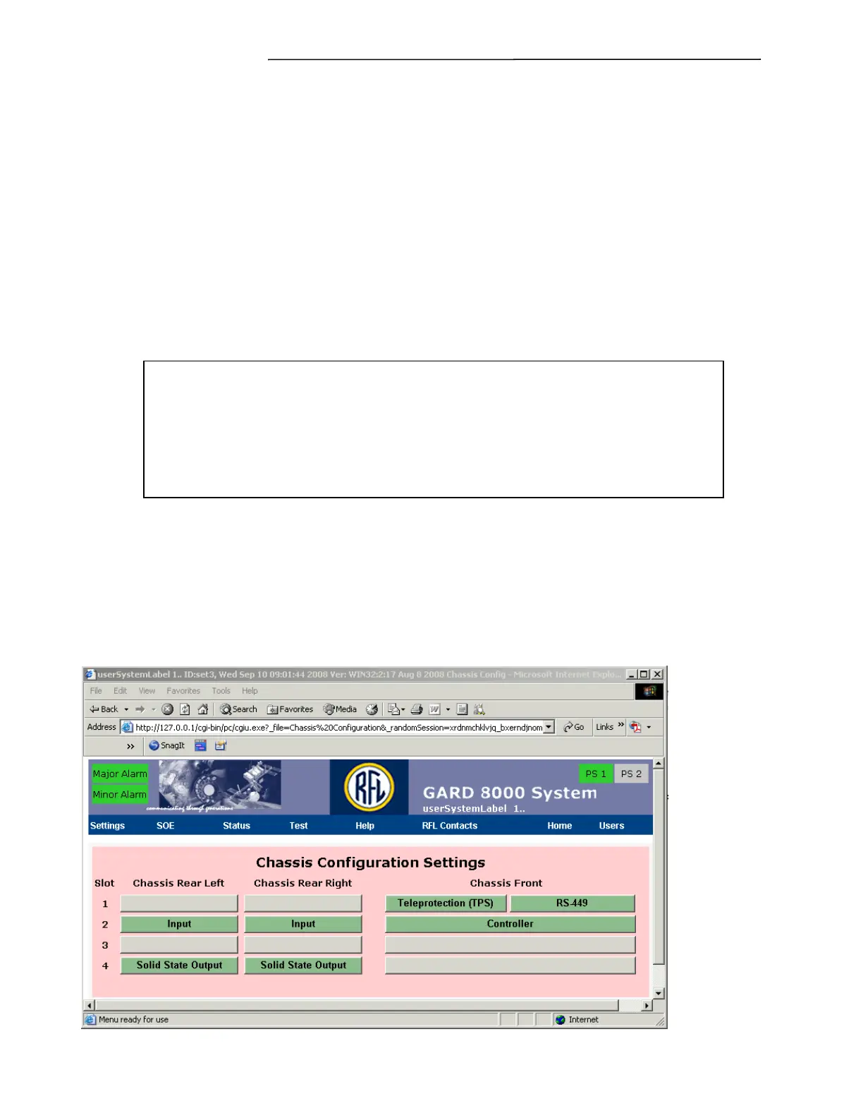
Chassis Configuration Settings
GARD 8000 SYS RFL Electronics
April 1, 2012 7-8 973.334.3100
Select Module Disable to save the settings and to disable the I/O module in the GARD chassis.
Start of Logic Range
This value can be obtained from the logic diagram and will establish which logic bit the module will
begin to place data onto the logic bus (3-506). Careful consideration must be given when entering
logic bit settings. Improper settings will result in a Logic Bus Error, and a unit that does not
operate properly. Logic bit assignments should never be duplicated within a chassis.
Save
Select the Save button to save the module settings without changing the module enable/disable status.
Once all the entries have been made, click on the SAVE button. A screen similar to the one shown in
Figure 7-6 will appear.
NOTE
Outputs that are mapped to “NOT USED” may be either open or closed, depending
on a variety of factors. It is a good practice to disable any outputs through the
output programming page if they are not mapped. This will ensure that they are
not mapped.