Installation and Commissioning
GARD 8000 SYS RFL Electronics
November 28, 2017 4-22 973.334.3100
This feature is practical when performing local operations and other user’s (temporarily) should not be
allowed access to the unit. The user ID and user’s password remain valid, and access is simply restored
by ‘enable’.
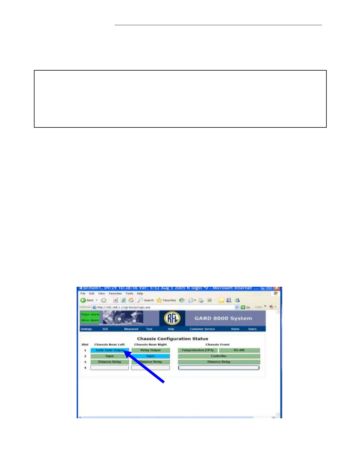
4.6.1.3 VERIFYING CHASSIS CONFIGURATION STATUS
Once a successful connection to the GARD 8000 is established, click on ‘Home’ in order to display a
current Chassis Configuration Status as shown below.
This webpage is a pictorial representation of the front and rear of the 3U chassis. The two left columns
represent the rear of the 3U chassis, and the right column represents the front of the 3U chassis. The
boxes represent actual module locations. Boxes that have text in them indicate that a module is
plugged into that slot. Boxes without text indicate a blank slot.
The Chassis Configuration Status screen shows an actual hardware configuration and the status of each
module configured in the shelf. The following colors indicate a status of each module:
Green Normal Condition (modules configured, operating properly).
Blue Modules disabled, Out of Service condition.
Yellow Modules enabled, but in Minor Alarm.
Red Modules in Major Alarm
Each of the installed modules can be configured, by clicking on a box. Selecting a module will bring
up that modules configuration settings screen.
Modules in Blue
“Disabled”
Note
There is no ‘backdoor’ for the Admin password. The default password is ‘Admin’ but when
changed, the actual password has to be used. Please contact the factory for password recovery
procedure.
Only the Admin can access the administrator page. Any number of users can be added by the
administrator, with individual access levels.