7. Check the left and right margins of the printed grid pattern.
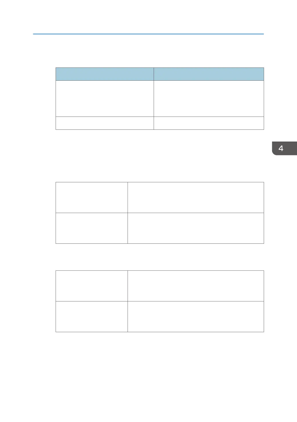
Left and right margins of the grid pattern Solutions
Within 2.5 to 3.0 mm
Retrieve the settings for SP4-012-007/008
(Scanner Edge Margin: DF: left/right) to the
values before adjustment. This completes
adjustment.
Outside 2.5 to 3.0 mm Adjust the margin as described below.
Margin Adjustments
1. Set SP2-104 (paper edge detection delay adjustment) as described below in SP
mode.
Right edge adjustment: Set SP2-104-001 (right edge of plain paper) as described in the table
below.
To increase the margin
Add the value so that the margin becomes 3.0 mm.
Example: If the current margin is 1.0 mm, enter +2.0 mm as
the current value.
To decrease the margin
Subtract the value so that the margin becomes 3.0 mm
Example: If the current margin is 4.5 mm, enter -1.5 mm as
the current value.
Left edge adjustment: Set SP2-104-002 (left edge of plain paper) as described in the table
below.
To increase the margin
Subtract the value so that the margin becomes 3.0 mm.
Example: If the current margin is 1.0 mm, enter -2.0 mm as
the current value.
To decrease the margin
Add the value so that the margin becomes 3.0 mm.
Example: If the current margin is 4.5 mm, enter +1.5 mm as
the current value.
2. Print the grid pattern again and check the right and left margins.
If the margin is between 2.5 and 3.0 mm, go to the next step.
3. Do SP2-104-031 (Paper Edge Detection Delay Adj: Automatic Conversion).
When the SP is done, the expected value based on the adjustment of the plain paper will be
reflected on the other type of paper.
Carriage Unit
413