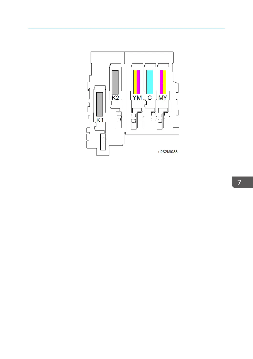
• There is one piezoelectric element for each print head: K1 (25), K2 (23), Y1M1(20), C (17), and
Y2M2 (15). An electric charge applied to the element makes it expand and discharge ink through
the print head nozzles and onto the paper below.
• At the beginning of a print job, the carriage moves left then back to the right, so that the DRESS
sensor (26) on the side of the carriage can detect the side edges of the paper below. Based on
these readings, the machine determines the image print start position.
• Ink level sensor 1 (13) checks the position of the feeler mounted on the side of the K1 ink sub tank.
Ink level sensor 2 (12) measures the positions of the feelers on the sides of the K2, C, Y, and M sub
tanks. The position of the feelers is used to determine how much ink needs to be supplied. While ink
level sensor 1 services only the K1 print head unit, and ink level sensor 2 services the other four sub
tanks.
• The temperature/humidity sensor (11) constantly measures the temperature and humidity inside the
machine, and then uses these readings to adjust operation of the machine.
• The head lift motor (10) can raise the carriage unit (1 mm or 2 mm) to increase the gap between
the print heads and thick paper to prevent ink abrasion. Two head lift sensors (3) control the raising
and lowering of the carriage with the head lift motor.
Printing
843