• This step is done for cleaning the K2, C, and YM print heads in order to position the suction cap
(print head cap for K1) correctly.
• If only the K1 print head is to be cleaned, the cleaning unit is positioned to start cleaning
immediately with the suction cap forward at [A].
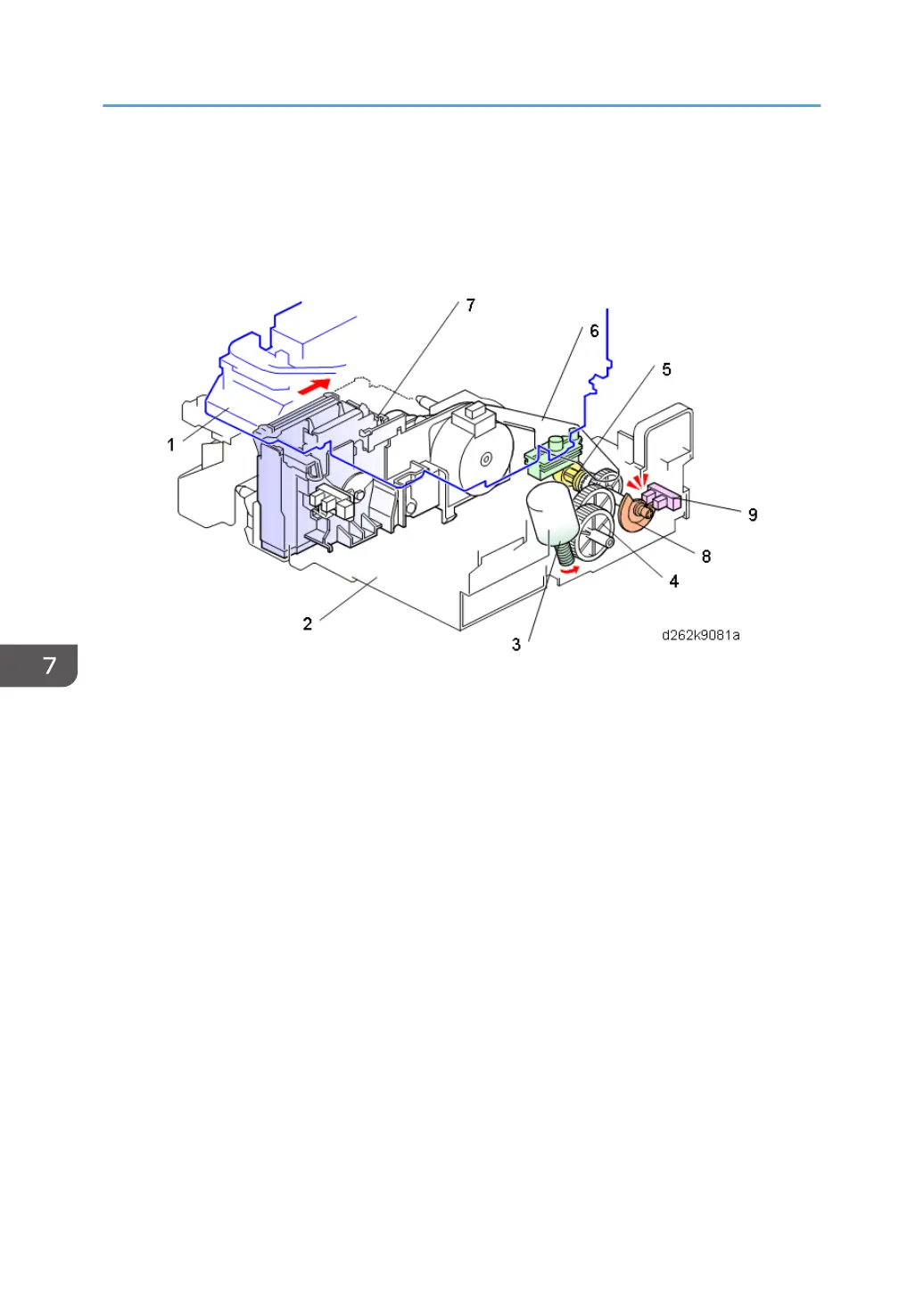
• At the start of the cleaning cycle, the carriage unit (1) positions itself over the maintenance unit (2).
• The lift motor (3) rotates in reverse and drives the gear train (4).
• The gears rotate a shaft with a large cam (5) between two swinging plates attached to the slide
arm (6) linked to the cleaning unit (7)
• When the cam pushes the front plate forward, the slide arm and cleaning unit move to the rear.
• When the slide actuator (8) (attached to the same shaft driven by the lift motor) activates the slide
sensor (9), the lift motor switches off with the cleaning unit at the rear.
Step 2: Raising the Suction Cap
7. Detailed Description
858