Home
Siemens
Telephone
HiPath 3000
Service Manual
Page 144 (Figure 3-32 UPSC-DR - Connectors)
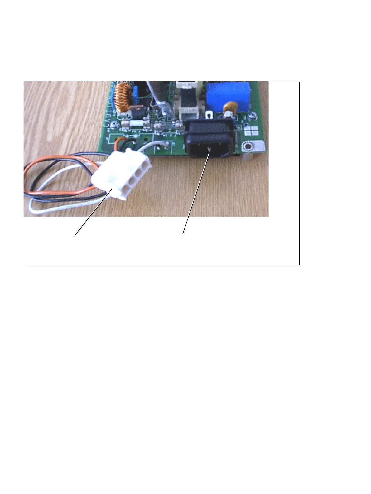
Siemens HiPath 3000 - Figure 3-32 UPSC-DR - Connectors
1144 pages
Manual
To Next Page
To Next Page
To Previous Page
To Previous Page
Loading...
Boards for HiPath 3000
P31003-
H3550-S4
03-4-76
20, 02/05
3-78
HiPath 30
00 V5.0
, HiPat
h 5000 V5.0
,
Ser
vice Ma
nual
boards.fm
Centr
al Bo
ards
Connectors
Figure
3-32
UPSC
-DR - Conne
ctors
Po
w
e
r
p
l
u
g
Connecto
r f
or batteries an
d
EPSU2-R (installe
d in the ECR)
143
145
Table of Contents
Main Page
Table of Contents
3
1 Important Information
19
Overview
19
Hipath 3000 V5.0, Hipath 5000 V5.0, Service Manual
19
Structure of this Electronic Service Manual
20
Hipath 3000 V5.0, Hipath 5000 V5.0 , Service Manual
21
Electrical Environment
22
Safety Information
23
Hipath 3000 V5.0, Hipath 5000 V5.0 , Service Manual
23
Safety Information: Dangers
24
Hipath 3000 V5.0, Hipath 5000 V5.0 , Service Manual
25
Safety Information: Warnings
26
Hipath 3000 V5.0, Hipath 5000 V5.0 , Service Manual
27
Safety Information: Cautions
27
General Information
28
Hipath 3000 V5.0, Hipath 5000 V5.0 , Service Manual
29
Reporting Accidents
30
What to Do in an Emergency
30
Hipath 3000 V5.0, Hipath 5000 V5.0 , Service Manual
31
Safety Information for Australia (for Australia Only)
31
Privacy and Data Security
32
Information on the Intranet
33
2 System Data
35
Overview
35
Hipath 3000
36
Introduction
36
Design and Dimensions of Hipath 3800
37
Design and Dimensions of the Hipath 3000 Systems
37
Figure 2-1 Hipath 3800 Dimensions
38
Design and Dimensions of Hipath 3750
39
Design and Dimensions of Hipath 3550
41
Design and Dimensions of Hipath 3350
42
Figure 2-4 Hipath 3350 Dimensions
42
Design and Dimensions of Hipath 3700
43
Figure 2-5 Hipath 3700 Dimensions
43
Design and Dimensions of Hipath 3500
44
Figure 2-6 Hipath 3500 Dimensions
44
Design and Dimensions of Hipath 3300
45
Figure 2-7 Hipath 3300 Dimensions
45
Hipath 3800 System Environment
46
System Environment of the Hipath 3000 Systems
46
Hipath 3750 and Hipath 3700 System Environment
47
Hipath 3550 System Environment
48
Hipath 3350 System Environment
49
Hipath 3500 System Environment
50
Hipath 3300 System Environment
51
Hipath 5000
54
System-Specific Capacity Limits for Hipath 3000, Hipath 5000
55
Technical Specifications for Hipath 3000
57
Interface-To-Interface Ranges
58
Numbering Plan for Hipath 3000/5000
59
Technical Specifications and Compliance to Hipath 3000
60
CE Compliance (Not for U.S.)
60
Compliance with US and Canadian Standards (for U.S. and Canada Only)
60
FCC Compliance
61
FCC Rules, Part 15
61
FCC Rules, Part 68
61
Equipment Attachment Limitations
64
Industry Canada Compliance
64
Ren
64
SAFETY International
65
Environmental Conditions
66
Electrical Operating Conditions
66
Mechanical Operating Conditions
66
Table 3-1 Hipath 3000 - Functional Overview of All Boards Used
67
Table 3-2 Hipath 3000 - Overview of All Boards Models Used
74
3 Boards for Hipath 3000
86
Central Boards
87
Table 3-5 CBCC - S Interface Assignment (RJ45 Jacks)
87
Cbcc
88
Table 3-6 CBCC - V.24 Interface Assignment (SUB-D Plug)
88
Table 3-7 CBCC - LAN Connector Assignment (RJ45 Jack) Via LIM
88
Cbrc
91
Figure 3-2 CBRC Board (S30810-Q2935-Z301)
93
Table 3-13 CBRC - V.24 Interface Assignment (SUB-D Plug)
95
Table 3-14 CBRC - LAN Connector Assignment (RJ45 Jack) Via LIM
95
Cbcpr
98
Table 3-17 CBCPR - V.24 Interface Assignment (SUB-D Plug)
100
Table 3-18 CBCPR - LAN Connector Assignment (RJ45 Jack)
100
Cbsap
101
Figure 3-4 CBSAP Board (S30810-Q2314-X)
102
Figure 3-5 CBSAP - Front Panel
103
Table 3-19 CBSAP - V.24 Interface Assignment (SUB-D Plug)
104
Table 3-20 CBSAP - LAN Connector Assignment (RJ45 Jack)
104
Cma
105
Figure 3-6 CMA with Spacing Bolts
105
Cms
106
Cr8N
110
Figure 3-8 CR8N (S30810-Q2513-X100)
111
Table 3-22 CR8N - LED Statuses
111
CUC and CUCR
112
CUP and CUPR
113
Dbsap
114
Figure 3-13 DBSAP (S30807-Q6722-X)
114
Figure 3-14 DBSAP on the Backplane of the Expansion Cabinet
115
Imodn
116
Lim
117
Figure 3-15 LIM in Hipath 3750 and Hipath 3700 - Procedure for
118
Figure 3-16 LIM in Hipath 3750 and Hipath 3700 - Adapter Cable
118
Figure 3-17 LIM in Hipath 3750 and Hipath 3700 - Attachment of the
119
Figure 3-18 CBSAP with LIMS Module Plugged in
120
Lims
120
Luna2
122
Figure 3-19 LUNA2 Front Panel
124
Figure 3-20 LUNA2 Slots in the Basic Cabinet (with Outer Panel Mounted)
126
Figure 3-21 LUNA2 Slots in the Expansion Cabinet (with Outer Panel Mounted)
127
Figure 3-22 Rear View of the BSG 48/38 Battery Cabinet (S30122-K5950-F300)
129
MMC
131
Psup
133
Upsc-D
134
Figure 3-25 UPSC-D (S30122-K5660-M300)
136
Figure 3-26 UPSC-D (S30122-K5660-M300)
136
Figure 3-27 UPSC-D - Switches and Leds
137
Figure 3-28 UPSC-D - Connectors
138
Upsc-Dr
139
Figure 3-31 UPSC-DR - Switches and Leds
143
Figure 3-32 UPSC-DR - Connectors
144
Upsm
145
Figure 3-33 Front and Rear Views of the UPSM (S30122-K5950-S100)
148
Figure 3-35 Rear View of the BSG 48/38 Battery Cabinet (S30122-K5950-F300)
150
Figure 3-36 Connections between the BSG 48/38 Battery Cabinet and
151
Peripheral Boards
152
DIU2U (for U.S. Only)
152
Figure 3-37 DIU2U Adapter Cable C39195-A7269-B625 (for U.S. Only)
153
Figure 3-38 DIU2U (for U.S. Only) - Front Panel (S30810-Q2216-X)
154
Diun2
156
Hxgm3
160
Figure 3-41 HXGM3 - Interfaces
162
Hxgs3, Hxgr3
166
Figure 3-44 HXGS3 (S30810-Q2943-X)
168
Figure 3-45 HXGR3 (S30810-K2943-Z)
168
Figure 3-46 HXGS3/HXGR3 - Interfaces
169
Figure 3-48 HXGS3 - Securing Clips for Fan Kit
174
Figure 3-49 HXGS3 - Connection of the Fan Kit
174
Ivml8, Ivml24
175
Figure 3-50 IVML8 and IVML24 - Packing Protection Covering
176
Ivmnl, Ivmn8
180
Figure 3-53 IVMNL/IVMN8 - Packing Protection Covering
181
Figure 3-54 IVMNL/IVMN8 - Front Panel (S30122-H7688-X -X100)
182
IVMP8 (Not for U.S.), IVMP8R (Not for U.S)
185
Figure 3-55 IVMP8 and IVMP8R (Not for U.S.) - Packing Protection Covering
186
Figure 3-56 IVMP8, IVMP8R (S30122-Q7379-X100, -K7379-Z100)
187
Ivms8, Ivms8R
190
Figure 3-57 IVMS8 and IVMS8R - Packing Protection Covering
191
Figure 3-58 IVMS8 and IVMS8R (S30122-Q7379-X, -K7379-Z)
192
Figure 3-60 PBXXX (S30810-Q6401-X) Front Panel
196
Pbxxx
196
P31003-H3550-S403-4-7620
198
SLA8N (Not for U.S.), SLA16N, SLA24N
198
SLC16 (Not for U.S.), SLC16N (Not for U.S.)
205
Figure 3-62 SLC16 (S30810-Q2922-X) (Not for U.S.)
206
Figure 3-63 SLC16N (S30810-Q2193-X100) (Not for U.S.)
206
Table 3-59 SLC16, SLC16N (Not for U.S.) - Cable Assignment
208
Table 3-60 Hipath 3750, Hipath 3700 - Maximum Number of SLA24N and
210
Table 3-61 Hipath 3550 - Maximum Number of Corded Telephones
212
Table 3-62 Hipath 3550 - Maximum Number of Corded Telephones
212
Table 3-63 Hipath 3550 - Maximum Number of Corded Telephones Depending on the Number of BS3/3 Base Stations Connected to
212
Figure 3-64 Base Station Power Supply Via One U P0/E Interface (Not for U.S.)
214
Figure 3-65 Base Station Power Supply Via Two U P0/E Interfaces (Not for U.S.)
215
Figure 3-66 BS3/3 Power Supply Via Three U P0/E Interfaces (Not for U.S.)
216
Figure 3-67 EPSU2 - Indicators and Ports
218
Figure 3-69 SLCN (S30810-Q2193-X300) - Leds on the Front Panel
222
SLCN (Not for U.S.)
222
Table 3-66 SLCN:LED Statuses
223
Table 3-67 SLCN - SIVAPAC Connector Assignment on the Backplane
224
Table 3-68 SLCN - Connector Panel Assignment with RJ45 Jacks
225
Table 3-69 SLCN - Connector Panel Assignment with SIPAC 1 SU Connectors
227
Figure 3-70 SLMA/SLMA8 - Leds on the Front Panel
229
Slma, Slma8
229
Table 3-70 SLMA/SLMA8 - LED Statuses
230
Table 3-71 SLMA/SLMA8 - SIVAPAC Connector Assignment on the Backplane
232
Table 3-72 SLMA/SLMA8 - Connector Panel Assignment with RJ45 Jacks
233
Table 3-73 SLMA/SLMA8 - Connector Panel Assignment with CHAMP Jack
235
Table 3-75 SLMA, SLMA8 - Connector Panel Assignment with SIPAC 1 SU
238
Figure 3-71 SLMO2/SLMO8 - Leds on the Front Panel
239
Slmo2, Slmo8
239
Table 3-76 SLMO2 and SLMO8 - LED Statuses
240
Table 3-77 SLMO2/SLMO8 - SIVAPAC Connector Assignment on the
242
Table 3-78 SLMO2/SLMO8 - Connector Panel Assignment with RJ45 Jacks
243
Table 3-79 SLMO2/SLMO8 - Connector Panel Assignment with CHAMP
245
Table 3-81 SLMA, SLMA8 - Connector Panel Assignment with SIPAC 1 SU
248
SLMO8 (Not for U.S.), SLMO24
249
Table 3-82 SLMO8 (Not for U.S.) and SLMO24 - LED Statuses
250
Table 3-83 SLMO8 (Not for U.S.), SLMO24 - Cable 1 Assignment (SU Xx8)
251
Table 3-84 SLMO8 (Not for U.S.), SLMO24 - Cable 2 Assignment (SU Xx9)
252
Table 3-85 SLMO24 - Assignment (SU Xx8, Xx9) (for U.S. Only)
253
Slu8
255
Slu8R
256
Figure 3-75 STLS2 (Not for U.S.), STLS4 Interfaces
257
STLS2 (Not for U.S.), STLS4
257
Table 3-88 STLS4 Module Interface Assignments (for U.S. Only)
258
Figure 3-76 Sample Pin Assignments in MW Jacks (Not for U.S.)
260
Figure 3-77 Wiring and Ranges for S Bus Jacks (Not for U.S.)
261
Figure 3-79 S Bus Wiring from STLS4 Port or Optiset E ISDN Adapter
263
Stls4R
264
Table 3-89 STLS4R Contact Assignments
265
Stlsx2, Stlsx4, Stlsx4R
266
Figure 3-82 Pin Assignments in MW Jacks
269
Figure 3-83 Wiring and Ranges for S Bus Jacks
270
Figure 3-84 STMD3 (S30810-Q2217-X10/-X110) - Leds on the Front Panel
271
Stmd3
271
Table 3-91 STMD3 - LED Statuses
272
Table 3-92 STMD3 - SIVAPAC Connector Assignment on the Backplane
273
Table 3-93 STMD3 - Connector Panel Assignment with RJ45 Jacks
274
Table 3-95 STMD3 - Connector Panel Assignment with SIPAC 1 SU
276
Stmd8
277
Table 3-96 STMD8 - LED Statuses (H301 to H308)
278
Figure 3-86 S Trunk Connection (Example for Hipath 3750)
279
Figure 3-87 S
279
Figure 3-88 S Networking Options (Not for U.S.) (Examples for Hipath 3750)
281
Figure 3-89 S Bus to the STMD8 over the MDFU or MDFU-E (Not for U.S.)
282
Figure 3-91 S Bus - Example of Jack Assignment (Not for U.S.)
283
Table 3-97 STMD8 - Cable and Connector Assignment (Not for U.S.)
284
Table 3-98 STMD8 - Assignment (Suxx8) (for U.S. Only)
285
Stmi2
287
Table 3-99 STMI2 - Board Variants
287
Figure 3-93 STMI2 (S30810-Q2316-X100) - HGA Slots
288
Table 3-100 STMI2 - Extension Modules
288
Table 3-102 STMI2 - LAN Interface Assignment (RJ45 Jacks)
292
Tiel
293
Figure 3-96 E&M Interface Type 1 (Not for U.S.)
298
Figure 3-97 E&M Interface Type 1A (Not for U.S.)
299
Figure 3-98 E&M Interface Type 1B or 5 (Not for U.S.)
300
Figure 3-99 E&M Interface Type 2 (Not for U.S)
301
TLA2 (Not for U.S.), TLA4 (Not for U.S.), TLA8 (Not for U.S.)
308
Figure 3-103 TLA4R (Not for U.S.) Interfaces (S30817-Q923-Zxxx)
310
Table 3-109 TLA4R (Not for U.S.) Contact Assignments
310
TLA4R (Not for U.S.)
310
Figure 3-104 TM2LP - Front Panel (S30810-Q2159-XXXX)
312
Tm2Lp
312
Table 3-110 TM2LP - LED Statuses
313
Table 3-111 TM2LP - SIVAPAC Connector Assignment on the Backplane
314
Table 3-112 TM2LP - Connector Panel Assignment with RJ45 Jacks
316
Table 3-113 TM2LP - Connector Panel Assignment with CHAMP Jack
317
Table 3-114 TM2LP - Connector Panel Assignment with SIPAC 1 SU
318
TMAMF (for Selected Countries Only)
319
Figure 3-106 Pin Assignments of the TMAMF Diagnostic Cable
320
Table 3-117 TMAMF - Cable Assignment
322
Figure 3-107 TMC16 (for U.S. Only) (S30810-Q2485-X) - Front Panel
323
TMC16 (U.S. Only)
323
Table 3-118 TMC16 (for U.S. Only) - LED Statuses
324
Table 3-119 TMC16 (for U.S. Only) - SIVAPAC Connector Assignment on
325
Table 3-121 TMC16 (for U.S. Only) - Connector Panel Assignment with SIPAC 1 SU Connectors (Cable for Ports 1 - 16)
327
TMCAS (for Selected Countries Only)
328
TMDID (for U.S. Only)
338
Figure 3-111 TMDID (for U.S. Only) (S30810-Q2452-X) - Front Panel
339
TMDID8 (for U.S. Only)
343
Tmew2
346
Figure 3-113 TMEW2 - Front Panel (S30810-Q2292-X100)
347
Figure 3-114 TMGL4 (for U.S. Only) - Interfaces (S30810-Q2918-X)
350
TMGL4 (for U.S. Only)
350
Figure 3-115 TMGL4R (for U.S. Only) (S30810-K2918-Z)
352
TMGL4R (for U.S. Only)
352
Figure 3-116 TMGL8 (for U.S. Only) (S30810-K2703-Z)
354
TMGL8 (for U.S. Only)
354
Figure 3-117 TML8W (Not for U.S.) (S30817-Q626-Axxx, -Bxxx)
356
TML8W (Not for U.S.)
356
Figure 3-118 TMQ4 (for U.S. Only) (S30810-Q2917-X)
359
TMQ4 (for U.S. Only)
359
Figure 3-119 TMST1 (for U.S. Only) (S30810-Q2920-X)
361
TMST1 (for U.S. Only)
361
TMS2 (Not for U.S.)
364
Figure 3-122 S 2M Trunk Connection
367
Figure 3-124 S 2M - NT Connection (Not for U.S.)
368
Figure 3-125 S 2M Connection to Deutsche Telekom NT (for Germany Only)
369
Figure 3-126 S
370
Figure 3-127 TST1 (for U.S. Only) (S30810-Q2919-X/S30810-K2919-Z)
371
TST1 (for U.S. Only)
371
TS2 (Not for U.S.), TS2R (Not for U.S.)
373
Figure 3-130 S 2M Trunk Connection
376
Figure 3-131 S 2M - NT Connections for Spain and Portugal
377
4SLA (Not for U.S.), 8SLA, 16SLA (Not for U.S.)
378
Figure 3-132 4SLA (Not for U.S.), 8SLA - Interfaces
378
8Slar
381
Options
383
Alum4
383
Figure 3-136 ALUM4 - Interfaces (S30817-Q935-A)
384
Amom
387
ANI4 (for Selected Countries Only)
389
Figure 3-140 ANI4 (for Selected Countries Only) - Installation Steps
392
ANI4R (for Selected Countries Only)
393
Figure 3-141 ANI4R (for Selected Countries Only) (S30807-Q6917-Z103)
393
Announcement and Music Modules
395
Evm
398
Figure 3-144 EVM (S30807-Q6945-X) - Interfaces
399
EXMNA (for U.S. Only)
400
Figure 3-145 EXMNA (for U.S. Only) (S30807-Q6923-X)
400
Figure 3-147 GEE8 (Not for U.S.) (S30817-Q664-XXXX)
402
GEE8 (Not for U.S)
402
GEE12 (nor for U.S.), GEE16 (Not for U.S.), GEE50 (Not for U.S.)
403
Figure 3-149 HOPE (for U.S. Only) (S30122-Q7078-X; S30122-Q7079-X)
405
HOPE (for U.S. Only)
405
Figure 3-150 OPAL (C39195-A7001-B130)
407
OPAL and OPALR
407
Figure 3-151 OPALR (C39195-A7001-B142)
408
PFT1 (Not for U.S.), PFT4 (Not for U.S.)
409
Figure 3-153 Installation Location of PFT1 and PFT4 (MDFU/MDFU-E)
410
Real
412
Figure 3-155 Installation Location of the REAL Board
413
Table 3-163 REAL - Cable and Connector Assignment
415
Reals
416
Figure 3-157 REALS (S30807-Q6629-X)
417
Figure 3-158 REALS Slots in the Basic Cabinet (with Outer Panel Mounted)
418
Table 3-164 REALS - SIVAPAC Connector Assignment on the Backplane
419
STBG4 (for France Only)
421
Strb, Strbr
422
Table 3-166 STRB Contact Assignments
425
V24/1 (Not for U.S.)
427
Adapter
429
Table 3-169 V.24 Adapter Assignment (C39334-Z7080-C2)
429
Figure 3-166 V.24 Cable Assignment (C30267-Z355-A25)
430
V.24 Cable
430
4 Installing Hipath 3000
431
Overview
431
Installing Hipath 3800
434
Installation Procedure
434
Installing Hipath 3800 (Standalone)
435
Selecting the Installation Site
435
For U.S. Only: AC Outlet
436
Unpacking the Components
437
Overview
438
Setting up the System Cabinets
438
Figure 4-1 Hipath 3800 - Setting up the Basic Cabinet
439
Setting up a Single Cabinet
439
Stacking Two Cabinets
440
Figure 4-2 Hipath 3800 - Positioning the Cabinet Feet
441
Figure 4-3 Hipath 3800 - Installing a Stacked Two-Cabinet System
442
Setting up a Two-Cabinet System Side by Side
443
Figure 4-4 Hipath 3800 - Installing a Two-Cabinet System Side by Side
444
Grounding the System
445
Not for U.S.: Grounding the System
445
For U.S. Only: Grounding the System
448
Figure 4-8 Hipath 3800 - Earth Ground Connection (for U.S. Only)
449
Checking the Grounding
450
Installing Hipath 3800 (19-Inch Cabinet)
451
Selecting the Installation Site
451
Figure 4-9 Hipath 3800 - System Cabinet with Plastic Cover
452
Figure 4-10 Hipath 3800 - Installation Examples in the 19-Inch Cabinet
453
For U.S. Only: AC Outlet
454
Table 4-3 Electrical Connection Values (USA Only)
454
Unpacking the Components
454
Mounting a System Cabinet Using Support and Angle Brackets
455
Mounting System Cabinets in the 19-Inch Cabinet
455
Figure 4-11 Hipath 3800 - Removing Cabinet Feet
456
Figure 4-12 Hipath 3800 - Installing System Cabinets in 19-Inch Cabinet
457
Grounding the System
458
Checking the Grounding
460
Board Slots in the Basic and Expansion Cabinet
461
Installing Boards (Configuration Notes)
461
Figure 4-14 Hipath 3800 - Board Slots in the Basic Cabinet
462
Figure 4-15 Hipath 3800 - Board Slots in the Expansion Cabinet
463
Inserting or Removing Boards
464
Figure 4-16 Hipath 3800 - Removing/Inserting the Board Using the Board
465
Figure 4-17 Installing the Board Shielding Cover
465
Figure 4-18 Hipath 3800 - Installing the LUNA2 Power Supply Unit
466
Figure 4-19 Hipath 3800 - Slots for LUNA2 and REALS in the Basic
467
Figure 4-20 Hipath 3800 - Slots for LUNA2 in the Expansion Cabinet
467
Figure 4-21 Hipath 3800 - Installing the REALS Board
468
Mounting Connector Panels (if Required)
469
Installing the SIVAPAC-SIPAC Board Adapter
471
Figure 4-23 Installing the SIVAPAC-SIPAC Board Adapter
472
Figure 4-24 Replacing the Board Lock
473
Initializing the Boards
474
Distribution of the PCM Highway
475
Figure 4-26 Hipath 3800 - PCM Highways in the Basic Cabinet
475
Figure 4-27 Hipath 3800 - PCM Highways in the Expansion Cabinet
476
Table 4-4 Maximum Number of Time-Division Multiplex Channels Required
477
Static Traffic Capacity
478
Connecting the Cable to the Backplane
479
Backplane of the Basic Cabinet
480
Figure 4-28 Hipath 3800 - Backplane (S30804-Q5392-X) of the Basic Cabinet
480
Figure 4-29 Hipath 3800 - Connectors and Jacks on the Backplane of the
481
Table 4-6 Hipath 3800 - Assignment of Connectors and Jacks on the
482
Expansion Cabinet Backplane
483
Figure 4-30 Hipath 3800 - Expansion Cabinet Backplane (S30804-Q5393-X)
483
Figure 4-31 Hipath 3800 - Connectors and Jacks on the Backplane of the
484
Connecting Cables between the Basic and Expansion Cabinet
485
Table 4-7 Hipath 3800 - Assignment of Connectors and Jacks on the
485
Connecting Peripherals to the SIVAPAC Connector on the Backplane
486
Figure 4-32 Hipath 3800 - Backplane of the Basic Cabinet with Mounted
488
Connecting Peripherals to the Connector Panels with RJ45 Jacks
489
Figure 4-33 Hipath 3800 - Connector Panels with RJ45 Jacks
489
CHAMP Jack
491
Figure 4-34 Hipath 3800 - Connector Panel with CHAMP Jack (for U.S. Only)
491
For U.S. Only: Connecting Peripherals to the Connector Panels with
491
Connecting Peripherals to the Connector Panels with
492
Figure 4-35 Hipath 3800 - Connector Panel with Two SIPAC 1 SU
492
SIPAC 1 SU Connectors
492
Using an External Main Distribution Frame or External Patch Panel
494
Using an External Main Distribution Frame MDFU-E S30805-U5283-X
495
Laying the Line Network and Jumpers on the MDFU-E
496
Mounting the Main Distribution Frame (MDFU-E)
496
Figure 4-37 Assignment (Numbering) of the Splitting/Jumper Strips
497
Figure 4-39 Patch Panel S30807-K6143-X
500
Inserting the External Patch Panel S30807K6143-X
500
Figure 4-40 Installing the External Patch Panel in the 19-Inch Cabinet
501
Installing the Patch Panel in a 19-Inch Cabinet
501
Connecting the Line Network to the External Patch Panel
502
Figure 4-41 Layout of the Patch Panel S30807-K6143-X for Different
502
Figure 4-43 S Patch Panel C39104-Z7001-B3
504
Inserting External S Patch Panel C39104-Z7001-B3
504
Figure 4-44 Installing the External S Patch Panel in the 19-Inch Cabinet
505
Installing the S
505
Patch Panel in the 19-Inch Cabinet
505
Connecting Lines to the External S Patch Panel
506
For U.S. Only: Connecting Network Facilities
508
Loading the System Software and Installing Subboards on the CBSAP
509
Connecting Workpoint Clients
510
Making Trunk and Networking Connections
510
Performing a Visual Inspection
511
Table 4-9 Visual Inspection Procedure
511
Installing Hipath 3750, Hipath 3700
513
Installation Prerequisites
513
Installation Procedure
514
Installing Hipath 3750
514
Selecting the Installation Site
517
For U.S. Only: AC Outlet
518
Unpacking the Components
519
Install MDFU or MDFU-E (Not for USA)
520
Overview
521
Setting up the System Cabinets
521
Figure 4-48 Hipath 3750 - Removing the Front and Rear Covers
522
Removing the Cabinet Covers
522
Mounting a One-Cabinet System on the Wall (for U.S. Only)
523
Setting up a Single Cabinet
523
Figure 4-50 Hipath 3750 Mounting a One-Cabinet System on the Wall
524
Stacking Two Cabinets
525
Figure 4-51 Hipath 3750 - Installing a Two-Cabinet System (Stacked)
526
Figure 4-52 Hipath 3750 - Mounting the Stabilizer Feet
527
Figure 4-53 Hipath 3750 - Wall-Mount Kit (for U.S. Only)
528
For U.S. Only: Mounting Two Cabinets Stacked on the Wall
528
Figure 4-54 Hipath 3750 Wall Mounting for a Stacked Two-Cabinet System
529
Figure 4-55 Hipath 3750 - Installing a Two-Cabinet System (Side by Side)
531
Setting up a Two-Cabinet System Side by Side
531
Setting up a Stacked Three-Cabinet System
532
Figure 4-56 Hipath 3750 - Installing a Three-Cabinet System (Stacked)
533
Figure 4-57 Hipath 3750 Seismic Anchors (for U.S. Only)
534
For U.S. Only: Installing the Seismic Anchors
534
Figure 4-58 Hipath 3750 Seismic Anchoring for Multiple Cabinets
535
Grounding the System
536
Not for U.S.: Grounding the System
536
For U.S. Only: Grounding the System
539
Figure 4-62 Hipath 3750 - Grounding Connector for Basic Cabinet
540
Checking the Grounding
541
Backplanes on the "8-Slot" Cabinets
542
Connecting the Cable to the Backplane
542
Figure 4-63 Hipath 3750 - Backplane on the "8-Slot" Basic Cabinet
542
Figure 4-64 Hipath 3750 - Backplane on the "8-Slot" Expansion Cabinets
543
Table 4-12 Jack Assignment on the "8-Slot" Backplane
543
Figure 4-65 Two-Cabinet "8-Slot" System - Connection Cables between BC and
545
Figure 4-66 Three-Cabinet "8-Slot" System - Connection Cables between BC
546
Connection between the MDFU or MDFU-E and Backplane
547
Figure 4-67 S 2M Adapter (SIPAC 1 SU - MW8 (RJ48C)) C39228-A7195-A12
549
Laying the Line Network and Setting Jumpers on the MDFU or
552
Mdfu-E
555
For U.S. Only: Connecting Network Facilities
556
Installing Hipath 3700 (19-Inch Cabinet)
557
For U.S. Only: AC Outlet
558
Selecting the Installation Site
558
Table 4-14 Electrical Connection Values (for U.S. Only)
558
Unpacking the Components
558
Mounting the System Cabinet in the 19-Inch Cabinet
559
Removing the Cabinet Covers
559
Figure 4-72 Hipath 3700 - Removing the Front and Rear Covers
560
Mounting the System Cabinet with Angle Brackets
561
Figure 4-73 Hipath 3700 - Installation in the 19-Inch Cabinet
562
Figure 4-74 Hipath 3700 - Mounting the Patch Panel
563
Mounting the Patch Panel in the 19-Inch Cabinet
563
Grounding the System
564
Checking the Grounding
566
Backplanes on the "8-Slot" Cabinets
567
Connecting the Cable to the Backplane
567
Figure 4-76 Hipath 3700 - Backplane on the "8-Slot" Basic Cabinet
567
Figure 4-77 Hipath 3700 - Backplane on the "8-Slot" Expansion Cabinets
568
Table 4-15 Jack Assignment on the "8-Slot" Backplane
568
Figure 4-78 Two-Cabinet "8-Slot" System - Connection Cables between BC
570
Figure 4-79 Three-Cabinet "8-Slot" System - Connection Cables between BC
571
Connecting the Patch Panel and Backplane
572
Figure 4-80 Patch Panel S30807-K6143-X
574
Figure 4-82 S
576
Figure 4-83 Laying Wire Pairs at the S Patch Panel
577
Figure 4-84 Stripping the Open-End Cable for the S Patch Panel
578
Figure 4-85 S 2M Adapter (SIPAC 1 SU - MW8 (RJ48C)) C39228-A7195-A12
579
Connecting the Line Network to the Patch Panel
580
Figure 4-86 Layout of the Patch Panel S30807-K6143-X for Different
580
Loading the System Software and Installing Subboards on the CBCPR
581
Configuration Notes
582
Figure 4-87 Slot Numbers and Widths in "8-Slot" BC, EC1, and EC2
583
Figure 4-89 PCM Segments for a One-Cabinet System
587
Figure 4-90 PCM Segments for a Two-Cabinet System
588
Figure 4-91 PCM Segments for a Three-Cabinet System
588
Table 4-17 Hipath 3750 and Hipath 3700 - Static Traffic Capacity
589
Figure 4-92 Locking and Unlocking Boards
590
Inserting or Removing Boards
590
Connecting Workpoint Clients
591
Making Trunk Connections
591
Performing a Visual Inspection
592
Table 4-18 Visual Inspection Procedure
592
Installation Prerequisites
593
Installing Hipath 3550, Hipath 3350, Hipath 3500, and Hipath 3300
593
Installation Procedure
594
Table 4-19 Hipath 3550, Hipath 3350, Hipath 3500 and Hipath 3300 - System
594
Installing Hipath 3550 and Hipath 3350
595
Selecting the Installation Site
595
For U.S. Only: AC Outlet
597
Not for U.S.: Mounting the Main Distribution Frame (Hipath 3550 Only)
598
Unpacking the Components
598
Removing the System Housing Cover
600
Attaching the System to the Wall
602
Grounding the System and the Main Distribution Frame
603
Installing the Boards
605
Figure 4-98 Layout of CABLU S30269-Z41-A30 (Length = 3 M)
606
Laying the Line Network and Connection Cables
606
Attaching Ferrite
609
Configuration Notes
611
Figure 4-102 Hipath 3550 - Wall Housing System Overview
611
Table 4-21 Hipath 3550 and Hipath 3350 - Static Traffic Capacity
614
Connecting Workpoint Clients
615
Making Trunk Connections
615
Performing a Visual Inspection
615
Installation Versions
616
Installing Hipath 3500 and Hipath 3300 (19-Inch Housing)
616
For U.S. Only: AC Outlet
617
Selecting the Installation Site
617
Unpacking the Components
618
Figure 4-107 Hipath 3500 and Hipath 3300 - Wall Installation (for U.S.)
619
Not for U.S.: Attaching a Hipath 3500 and Hipath 3300 to the Wall
619
Installing a Hipath 3500 or Hipath 3300 in a Cabinet
620
Figure 4-108 Hipath 3500 and Hipath 3300 - Mounting the 19-Inch Cabinet
621
Grounding the System
622
Figure 4-109 Hipath 3500 and Hipath 3300 - Grounding
623
Installing the Boards
623
Connecting Cables and the Line Network
624
Figure 4-110 Hipath 3500 and Hipath 3300 - Connection Cable to ECR
624
Configuration Notes
625
Figure 4-111 Hipath 3500 - Slot Levels in the 19-Inch Housing
625
Figure 4-112 Hipath 3300 - Slot Levels in the 19-Inch Housing
626
Connecting Workpoint Clients
628
Making Trunk Connections
628
Performing a Visual Inspection
628
5 Starting up Hipath 3000
629
Overview
629
Not for U.S.: Entering the System Number
630
Startup Procedure
630
Table 5-1 Hipath 3800 - Startup Procedure
630
Starting up Hipath 3800
630
Supplying the System with Power
631
Table 5-2 RUN LED - LED Status Meaning
631
Assigning Station Numbers
632
Carrying out a System Reload
634
Carrying out the Country Initialization and Selecting the Password Type
635
Table 5-3 Entering the Country Code and Selecting the Password Type
636
Customer-Specific Programming
638
Table 5-5 Hipath 3750 and Hipath 3700 - Startup Procedure
639
Supplying the System with Power
640
Table 5-6 RUN LED - LED Status Meaning
640
Assigning Station Numbers
641
Carrying out a System Reload
643
Customer-Specific Programming
646
Performing a System Check
646
Table 5-9 Startup Procedure
647
Starting up Hipath 3550, Hipath 3350, Hipath 3500, Hipath 3300
647
Table 5-10 RUN LED - LED Status Meaning
648
Supplying the System with Power
648
Assigning Station Numbers
649
Carrying out a System Reload
651
Customer-Specific Programming
654
6 Hipath 5000 Startup and Administration
655
Overview
655
Introduction
656
Software Structure
659
Table 6-1 Feature Server Components
661
Notes on Open Numbering in a Hipath 3000/5000 Network
662
Installation Requirements
663
Prerequisites for a Single-PC Solution
664
Hipath 5000
664
Preparing for Installation
666
Table 6-5 Hipath 5000 - Preparing for Installation
666
Integrating the Hipath 5000 Server in the Customer LAN
667
Hipath 5000 Installing Standard Components
668
Overview
668
Table 6-6 Software Components and Master Setup Tools
668
Licensing
669
Starting the Installation
670
Installing Hipath Comscendo Service
675
Checking the Installation of the Hipath Comscendo Service
683
Installing Hipath Fault Management
684
Installing the TAPI Service Provider
688
Installing the Hipath Inventory Server Separately
689
Verifying Installation
694
Verifying the Start and Function of Hipath 5000 Services
694
Checking Entries in the Event Viewer
695
Modifying Hipath 5000 Components (Retro-Fitting, Updating, Deleting)
696
Performing Licensing
698
Optimizing Operating System Settings
699
Perform Hipath 5000 Basic Configuration
701
Configuring Hipath 5000 with Hipath Comscendo Service
702
Configuring Hipath 5000 Server as a Central Administration Unit in an
703
Creating a Central Customer Database for IP Networking
703
IP Network
703
Adding Individual Nodes for IP Networking
705
Hipath Manager PCM
707
Getaccount
708
Parameters for Call Data Export
708
Table 6-8 Getaccount - Data Record Structure
710
Figure 6-4 P 500 UPS - Front and Rear Panel
713
Connecting an Uninterruptible Power Supply to Hipath 5000
713
Table 6-9 P 500 UPS - Meaning of Displays, Switches and Jacks
714
7 Starting Hipath 3000 as a Gateway
715
Overview
715
Introduction
715
Starting Hipath 3800 as a Gateway
716
Prerequisites
716
Procedure for Installation and Startup
716
Table 7-1 Hipath 3800 as a Gateway - Procedure for System Installation and
716
Starting Hipath 3700 as a Gateway
718
Prerequisites
718
Procedure for Installation and Startup
718
Table 7-2 Hipath 3700 as a Gateway - Procedure for System Installation and
718
Starting Hipath 3500 as a Gateway
720
Prerequisites
720
Procedure for Installation and Startup
720
Table 7-3 Hipath 3500 as a Gateway - Procedure for System Installation and
720
Starting Hipath 3300 as a Gateway
722
Prerequisites
722
Procedure for Installation and Startup
722
Table 7-4 Hipath 3300 as a Gateway - Procedure for System Installation and
722
8 Licensing
725
Overview
725
Introduction
726
Licensing for Hipath 3000 V5.0, Hipath 5000 V5.0
728
Products and Components Subject to Mandatory Licensing
728
Grace Period
730
License Failure Period
730
Performing Licensing
731
Licensing Scenarios
736
Hipath 3000 as a Standalone System
736
Networked Hipath 3000 Systems Without Hipath 5000
737
Networked Hipath 3000 Systems with Hipath 5000
738
Upgrading to Hipath 3000 V5.0, Hipath 5000 V5.0
741
Combining Standalone Systems (Hipath 3000) to Form a Network with
744
Removing a Standalone System from a Network with Hipath 5000
746
Replacing License-Sensitive Hardware (Changing the MAC Address)
747
Licensing Opticlient Attendant
750
Opticlient Attendant V7.0 Connected to Hipath 3000 V5.0
750
Hipath 3000 V5.0
754
Upgrading Opticlient Attendant V6.0 -> V7.0 as Part of an Upgrade to
754
Upgrade Opticlient Attendant V6.0 -> V7.0 on Hipath 3000 < V5.0
756
Changing Licenses on an Opticlient Attendant V7.0 as Part of an Upgrade to Hipath 3000 V5.0
758
Protection against License Manipulation
760
Overview
761
9 Expanding and Upgrading Hipath 3000
761
Table 9-1 Startup Rules for Inserting and Removing Boards
762
Expanding Hipath 3000
762
Table 9-2 Startup Rules for Inserting and Removing Boards
764
Replacing Peripheral Boards for Hipath 3750 and Hipath 3700
764
Connecting a Printer
766
ECR with Hipath 3700, Hipath 3500, Hipath 3300 (Not for U.S. and Canada)
768
ECR Control, Display, and Connecting Elements
769
Figure 9-2 ECR Front Panel (155 X 440 X 380 MM)
769
Figure 9-3 ECR Rear Panel with Connecting Elements
770
Components
772
Installation Options
772
Expansion Cabinet Rack ECR with Batteries
773
Figure 9-5 ECR with Built-In Batteries
774
Installing Batteries
775
Expansion Cabinet Rack ECR with Batteries and EPSU2-R
778
Figure 9-7 ECR with Built-In EPSU2-R
780
Connecting a Fan (if Needed)
781
Figure 9-8 Connecting the Fan to the EPSU2-R
782
Figure 9-9 Placement of the Fan in the ECR
783
Connecting Special Equipment
784
Entrance Telephones
784
Figure 9-10 Connection Options for Entrance Telephones
784
Figure 9-11 Direct Connection of Entrance Telephones
784
Information on Third-Party Entrance Telephones
785
Connecting Speakers
787
Figure 9-14 Connecting Speakers to an Analog Trunk Port
788
Upgrading Hipath 3000 to V5.0
789
Hardware Upgrade
789
Software Upgrade
791
Figure 9-17 Flowchart for CDB Conversion from V4.0 -> V5.0 (Part 2 of 4)
793
Figure 9-18 Flowchart for CDB Conversion from V4.0 -> V5.0 (Part 3 of 4)
794
Figure 9-19 Flowchart for CDB Conversion from V4.0 -> V5.0 (Part 4 of 4)
795
10 Workpoint Clients
797
Overview
797
Optipoint 500
799
Optipoint 500 Entry
801
Optipoint 500 Telephones
801
Figure 10-2 Optipoint 500 Economy (Not for U.S.) - Standard Key Assignment
802
Optipoint 500 Economy (Not for U.S.)
802
Figure 10-3 Optipoint 500 Basic - Standard Key Assignment (Default)
803
Optipoint 500 Basic
803
Optipoint 500 Standard, Optipoint 500 Standard SL (for U.S. Only)
804
Figure 10-4 Optipoint 500 Standard - Standard Key Assignment (Default)
805
Optipoint 500 Advance
806
Figure 10-5 Optipoint 500 Advance - Standard Key Assignment (Default)
807
Connection Requirements for Hipath 3000
808
Connection
809
Connections on the Bottom of the Telephone
810
Figure 10-6 Optipoint 500 Connection Options
810
USB 1.1 Interface
811
Optipoint 500 Add-On Devices
812
Optipoint Key Module
812
Figure 10-8 Optipoint BLF
813
Optipoint BLF
813
Programming Add-On Devices
814
Figure 10-7 Optipoint Key Module
815
Possible Configurations for the Add-On Devices
815
Figure 10-10 Optipoint 500 Option Bays
816
Optipoint 500 Adapters
816
Optipoint Analog Adapter
817
Figure 10-12 Optipoint ISDN Adapter
818
Optipoint ISDN Adapter
818
Optipoint Phone Adapter
819
Figure 10-14 Example of a Host-Client Configuration
820
Optipoint Acoustic Adapter
821
Figure 10-16 y Cable for Optipoint Acoustic Adapter
822
Table 10-1 Floating Contacts on the Optipoint Acoustic Adapter
822
Optipoint Recorder Adapter
824
Possible Optipoint Adapter Configurations
825
Comparison of Optiset E Adapters and Optipoint 500 Adapters
826
Table 10-2 Comparison of Optiset E and Optipoint 500 Adapters
826
Table 10-3 System-Specific Maximum Configuration for U P0/E Workpoint Clients, Add-On Devices, and Adapters
827
Optipoint 600 Office
829
Optilog 4Me
832
Figure 10-19 Optilog 4Me
832
Optiset E Privacy Module
833
IP Telephony (Voice over IP)
834
Optipoint 410 and Optipoint 420
836
Optipoint 410 Entry
837
Optipoint 410 Telephones
837
Optipoint 410 Economy
839
Figure 10-21 Optipoint 410 Economy - Standard Key Assignment (Default)
840
Optipoint 410 Standard
841
Figure 10-22 Optipoint 410 Standard - Standard Key Assignment (Default)
842
Optipoint 410 Advance
843
Figure 10-23 Optipoint 410 Advance - Standard Key Assignment (Default)
844
Optipoint 420 Economy
845
Optipoint 420 Telephones
845
Figure 10-24 Optipoint 420 Economy - Standard Key Assignment (Default)
846
Optipoint 420 Economy Plus
847
Figure 10-25 Optipoint 420 Economy - Standard Key Assignment (Default)
848
Optipoint 420 Standard
849
Figure 10-26 Optipoint 420 Standard - Standard Key Assignment (Default)
850
Optipoint 420 Advance
851
Figure 10-27 Optipoint 420 Advance - Standard Key Assignment (Default)
852
Connection and Startup
853
Connections on the Bottom of the Telephone
854
Figure 10-28 Optipoint 410/Optipoint 420 - Connection Options
854
Table 10-5 Optipoint 410/Optipoint 420 - Description of Connections
855
Figure 10-29 Optipoint SLK Module
856
Optipoint 410 and Optipoint 420 Add-On Devices
856
Optipoint SLK Module
856
Figure 10-30 Optipoint 410 Display Module
857
Optipoint 410 Display Module
857
Possible Configurations for the Add-On Devices
859
Use of Optipoint 500 Adapters
859
Opticlient 130 V5.0
860
Hipath AP 1120
861
HG 1500: Determining the Number of HG 1500 Boards Required
862
Static Configuration Rules
862
Table 10-7 Technical Data (Resources) of the HG 1500 Boards Defined as
862
Dynamic Configuration Rules
864
Gateway Channels (DSP Channels)
864
Table 10-9 Number of Required Gateway Channels (HG 1500 Boards)
864
MOH Channels (G.711, G.723, G.729)
865
DMC (Direct Media Connection) Channels
866
IP Networking Channels (PBX Networking Channels)
866
Fax / Modem Channels
867
ISDN Routing/Ppp Channels
867
Determining the Number of HG 1500 Boards Required
868
Sample Calculation
871
Calculation Example 2: 96 IP Workpoint Clients and
872
Access to Hipath 3750, Hipath 3700
873
Calculation Example 4: IP Networking Connections and Voice over
875
Calculation Example 4: IP Networking Connections and Voice over PPP (ISDN Routing) to Hipath 3750, Hipath 3700
875
Calculation Example 5: Virtual Private Network VPN
876
Calculation Example 6: Connecting Teleworkers Via VPN
878
Remaining Bandwidth for Voice Transmission
880
Notes on the Maintenance of Gateway Channels Hipath
882
External AC Adapters
883
Optipoint Accessories
883
AC Adapter for Optipoint 410 and Optipoint 420
885
Figure 10-33 Example of a Corded and a Cordless Headset
886
Headsets
886
Attendant Console Versions
888
Optipoint Attendant
888
Opticlient Attendant
889
Mobile Telephones for Hipath Cordless Office
894
Figure 10-35 Gigaset S1 Professional
894
Gigaset S1 Professional
894
Figure 10-36 Gigaset SL1 Professional
895
Gigaset SL1 Professional
895
Figure 10-37 Gigaset M1 Professional
896
Gigaset M1 Professional
896
Gigaset Active M
897
Gigaset Active EX
898
Logging Mobile Telephones on to the System
900
Opening the Hipath 3000 Login Window
900
Logging on the Mobile Telephone
901
Checking the Login Status of the Mobile Telephones
902
Replacing, Locking, and Logging off a Mobile Telephone
902
Analog Telephones for Hipath 3000
903
ISDN Terminals for Hipath 3000
904
11 Hipath Cordless Office
905
Overview
905
Introduction
906
System Configuration
907
Technical Data for Base Stations
908
Figure 11-2 BS3/1 (BS3/S) and BS3/3 in the Outdoor Cover S30122-X7469-X
909
Power-Related Capacity Limits
910
Multi-SLC and System-Wide Networking
914
Figure 11-4 Incorrect DECT Configuration of Networked Hipath
916
Roaming
916
12 Service
919
Overview
919
Service and Maintenance Tasks
921
Automatic Customer Data Backup
921
Backing up the Customer Database (CDB Backup)
921
Customer Data Backup Without Hipath Software Manager
921
Manual Customer Data Backup with Hipath 3000
923
CDB Treatment When Replacing Central Hipath 3000 Hardware
924
Customer Data Backup with Hipath Software Manager
924
Effects of Hardware Changes on Customer Data
926
Inserting and Removing Hipath 3000 Boards
926
Exchanging Workpoint Clients
928
Hipath Software Manager
929
Relocate/Transfer Application Processor Software (APS)
929
Transferring an APS of Hipath 3000 by Replacing the MMC
929
APS Transfer
930
Upgrading Hipath 3000
935
Backing up System Components (Backup Manager)
937
Hipath User Management (Not yet Released)
939
Guided Maintenance
941
Central Control Boards
941
Diagnosis Options
941
Recording Hipath 3000 Board Status
941
Peripheral Boards
942
Power Supplies
942
Recording Hipath 3000 Trunk Status
944
Recording Station Status
945
Recording the Status of the Hipath 3000 V.24 Interfaces
946
Trace Options for Hipath 3000
947
Hipath Manager PCM Trace Monitor Applications
948
Figure 12-1 Trace Monitor
949
Starting and Exiting the Trace Monitor
949
Figure 12-2 the Screen Layout of the Trace Monitor
950
The Screen Layout of the Trace Monitor
950
General Functions
952
Exporting Trace Windows
953
Eventlog for Hipath 3000
955
Testing Telephones
955
Event Viewer for Hipath 5000 (Eventlog)
956
Figure 12-3 Hipath 5000 State Viewer
958
Hipath 5000State Viewer
958
Figure 12-4 Hipath 5000 Services
960
Hipath Fault Management
962
Analysis Using Customer License Agent (CLA)
963
Analysis Using Customer License Manager (CLM)
963
Licensing Analysis
963
Hipath 3000 Error Messages (Entries in the Eventlog for Hipath 3000)
966
Hipath 5000 Error Messages (Event Viewer Entries for Hipath 5000)
975
Correcting Errors
988
Automatic Error Correction
988
Manual Error Correction Without Hipath 3000 Manager E
988
Manual Error Correction with Hipath 3000 Manager E
989
Remote Service
990
Hipath 3000 Connection Options
991
Hipath 5000 Connection Options
992
Remote Administration of Hipath 3000 with Hipath 3000 Manager E
992
Remote System Administration
992
DTMF Remote Administration of Hipath 3000
993
Remote Correction of System Software (APS)
993
Remote Error Signaling
994
Controlled Release of a Remote Connection
995
Remote Administration and Access Using PPP
995
Remote Administration of Plus Products
995
Remote System Administration
995
Remote Error Signaling Using SNMP
996
Security Features
997
Access Security
997
Logon with User Name and Password
997
Pre-Determined User Groups and Their Access Rights
1000
System Access Options
1002
Customer Data Security
1003
Automatic Logging of Administration Procedures
1004
Format Identification and Command Entry
1004
Logging
1004
Issuing and Saving Log Data
1007
13 IP Fundamentals
1009
Overview
1009
IP Network Requirements
1010
General Introduction
1010
Protocol
1010
Standards Supported
1011
Qos - Quality of Service
1012
Network Analysis
1014
A System Programming Codes (Expert Mode Codes
1015
B Codes for Activating/Deactivating Features
1045
Table 3-115 Table
1045
Table 4-1 Table
1046
CIP Protocols and Port Numbers Used with Hipath 3000/5000 V5.0
1067
C.3 Hipath Comscendo Service
1071
Hipath FM Managed Systems
1073
Opticlient 130 V5.0
1077
Optipoint 400, Optipoint 410, Optipoint 420, Optipoint 600 Office
1078
Hipath
1080
Middleware for Call Control
1081
D Identifying System Power Requirements
1083
Hipath 3800 Board Power Requirement
1084
Hipath 3750 and Hipath 3700 Board Power Requirement
1086
P31003-H3550-S403-4-7620
1087
Hipath 3550 Board Power Requirement
1088
Hipath 3350 Board Power Requirement
1090
Hipath 3500 Board Power Requirement
1092
Hipath 3300 Board Power Requirement
1093
Workpoint Clients, Key Modules and Adapter Power Requirements
1094
Checking Whether the Output of a Power Supply Unit Is Sufficient
1096
Identifying the Primary System Power Requirement
1099
Figures 0
1101
Table of Contents
1113
Tables
1120
Abbreviations
1121
Index
1142
Other manuals for Siemens HiPath 3000
Operating Instruction
176 pages
Administration Manual
240 pages
User Guide
146 pages
Operating Manual
154 pages
Operating Instructions
146 pages
Opearting Instructions
107 pages
User Manual
79 pages
Quick Reference
6 pages
Related product manuals
Siemens HiPath 500
236 pages
Siemens HiPath 4000
162 pages
Siemens HiPath 1100
151 pages
Siemens HiPath 1120
151 pages
Siemens HiPath 8000
164 pages
Siemens HiPath 1150
151 pages
Siemens HiPath Series
125 pages
Siemens HiPath 1100 V7.0
46 pages
Siemens HiPath OpenOffice
214 pages
Siemens HiPath 1100 Series
29 pages
Siemens OPTIPOINT HIPATH 2000
141 pages
OpenStage 40 HFA HiPath 4000
120 pages

 Loading...