inst_h3.fm
P31003-H3550-S403-4-7620, 02/05
HiPath 3000 V5.0, HiPath 5000 V5.0, Service Manual
4-157
Installing HiPath 3000
Installing HiPath 3750, HiPath 3700
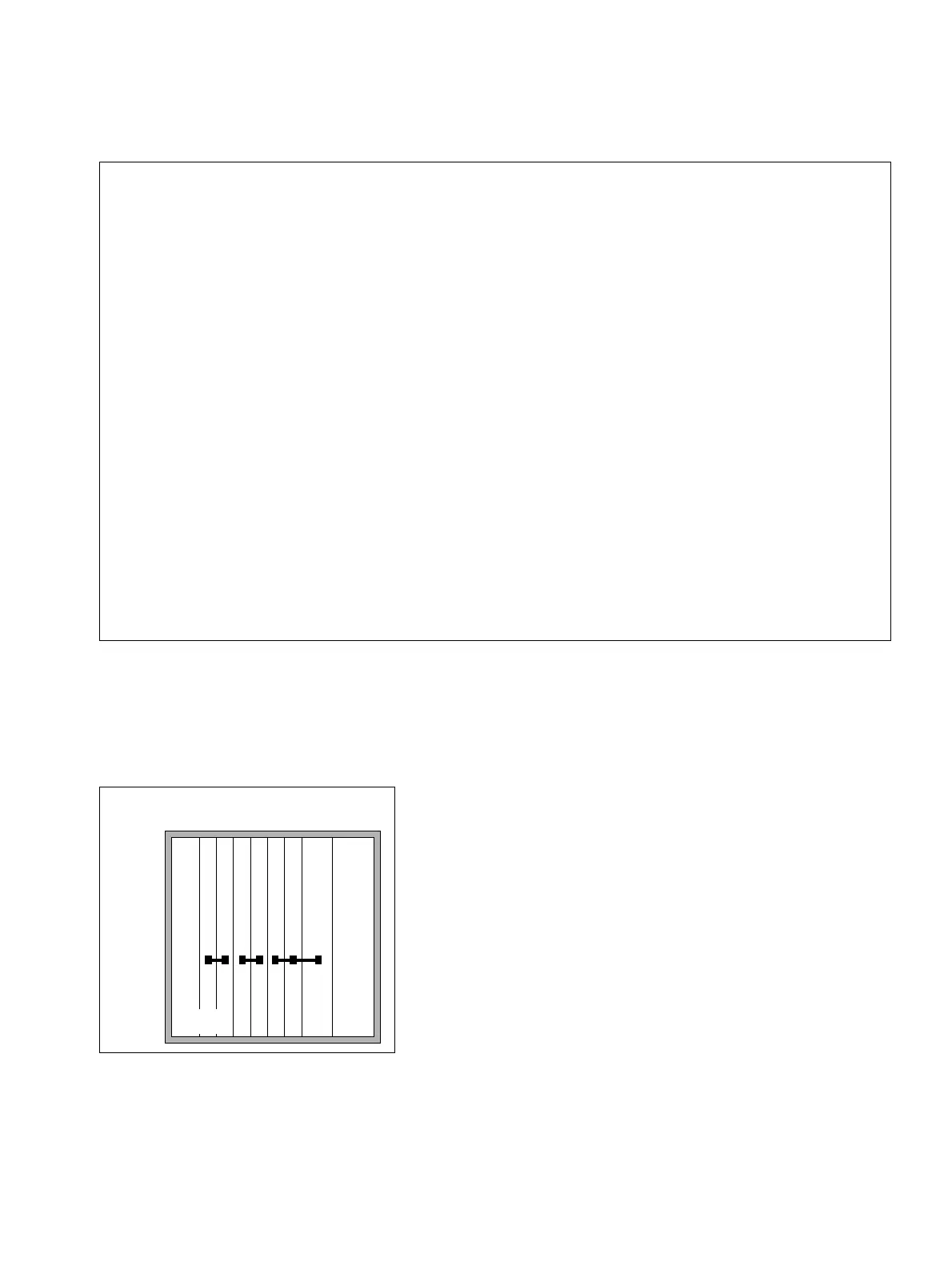
The figures below show the PCM segments (64 time-division multiplex channels each) for the
different HiPath 3750 and HiPath 3700 system configurations.
Single-cabinet system: PCM segments
7
Caution
The following board assignment rules must be observed to ensure that the system
works properly and without blocking:
● SLC16, SLC16N
– Maximum SLC16 or SLC16N per PCM segment. The SLC16 or SLC16N
should be configured alone on the PCM segment, where possible.
– Note the following information on the subject of multi-SLCs: “SLC16 and
SLC16N board distribution in HiPath 3750 and HiPath 3700 cabinets” on
page 3-143.
● IVML8, IVML24 (see Section 3.3.5)
– A maximum of one IVML8 or IVML24 per system.
– Then install them in the slot beside the power supply in the basic cabinet or
the expansion cabinets.
– No SLC16 or SLC16N may be inserted in the PCM segment of the IVML8/
IVML24.
– No SLMO24 may be inserted in the PCM segment of the IVML24.
– If a TMS2 is configured on the PCM segment of the IVML24, only a board
with a maximum of 8 ports may be inserted in the free slot.
● SLMO24
A maximum of two SLMO24s per PCM segment; the number of connected sta-
tions (hosts (master) and clients (slaves)) may not be more than 64.
Figure 4-89 PCM Segments for a One-Cabinet System
C
B
C
P
R
0
2
0
3
0
4
0
8
U
P
S
M
0
5
0
6
0
7
“8-slot” cabinets
BC

 Loading...