Service Parts Disassembly
Phaser 3610, WorkCentre 3615 Service Manual4-104
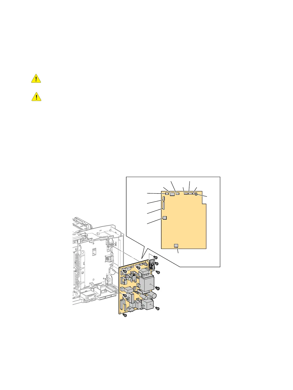
REP 5.3 LVPS
PL 5.1 Electrical (ESS PWB / LVPS) (3610)
Removal
WARNING: Allow the Fusing Assembly to cool before servicing the product.
CAUTION: Do not remove the LVPS from the protective bag until ready for installation. Always
wear a grounded wrist band while handling circuit boards.
1. Remove (REP 1.7 Left Side Cover (3610)) (REP 1.17 Lower Left Side Cover (3615)).
2. Remove the PWB LVPS. (Figure 1)
a. Disconnect all the connections to the LVPS.
b. Remove the wire harnesses from the clamps.
c. Remove 8 screws (silver, M3, 6mm) and 2 screws (silver, tapping, 8mm) that secure the
interlock switch bracket to remove the PWB LVPS.
CAUTION: The Interlock Switch is hard wired to the LVPS. Do not try to unplug it.
Figure 1
Replacement
1. Make sure the interlock switch is seated correctly on the pins before connecting to the LVPS.
2. Replace in reverse order.
s3610-074
P/J201
P/J220
P/J210
P/J241
P/J213
P/J211
P/J212
P/J250
P/J230 P/J240
P/J200
[DPP355]
b)
c)
a)

 Loading...