MPC5553/MPC5554 Microcontroller Reference Manual, Rev. 5
25-22 Freescale Semiconductor
25.7.2.3.4 Selecting a Nexus Client Register
When the NEXUS-ENABLE instruction is decoded by the TAP controller, the input port allows
development tool access to all Nexus registers. Each register has a 7-bit address index.
All register access is performed via the SELECT-DR-SCAN path of the IEEE 1149.1–2001 TAP
controller state machine. The Nexus controller defaults to the REG_SELECT state when enabled.
Accessing a register requires two passes through the SELECT-DR-SCAN path: one pass to select the
register and the second pass to read/write the register.
The first pass through the SELECT-DR-SCAN path is used to enter an 8-bit Nexus command consisting
of a read/write control bit in the lsb followed by a 7-bit register address index, as illustrated in
Figure 25-10. The read/write control bit is set to 1 for writes and 0 for reads.
The second pass through the SELECT-DR-SCAN path is used to read or write the register data by shifting
in the data (lsb first) during the SHIFT-DR state. When reading a register, the register value is loaded into
the IEEE 1149.1-2001 shifter during the CAPTURE-DR state. When writing a register, the value is
loaded from the IEEE 1149.1-2001 shifter to the register during the UPDATE-DR state. When reading
a register, there is no requirement to shift out the entire register contents. Shifting may be terminated after
the required number of bits have been acquired.
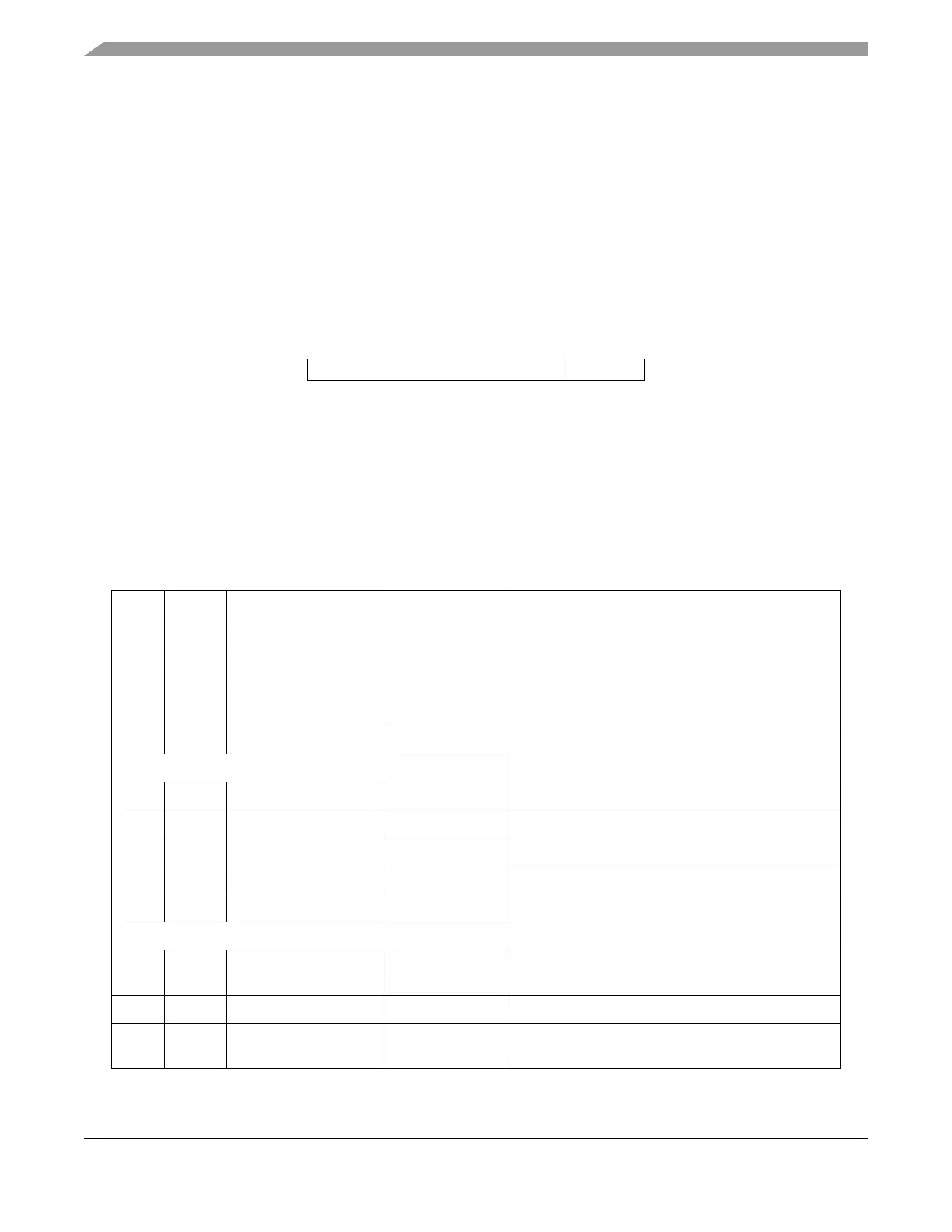
Table 25-16 illustrates a sequence that writes a 32-bit value to a register.
msb
lsb
7-bit register index R/W
Figure 25-10. IEEE 1149.1 Controller Command Input
Table 25-16. Write to a 32-Bit Nexus Client Register
Clock TMS IEEE 1149.1 State Nexus State Description
0 0 RUN-TEST/IDLE REG_SELECT IEEE 1149.1-2001 TAP controller in idle state
1 1 SELECT-DR-SCAN REG_SELECT First pass through SELECT-DR-SCAN path
2 0 CAPTURE-DR REG_SELECT Internal shifter loaded with current value of controller
command input.
3 0 SHIFT-DR REG_SELECT TDO becomes active, and write bit and 6 bits of
register index shifted in.
7 TCKs
11 1 EXIT1-DR REG_SELECT Last bit of register index shifted into TDI
12 1 UPDATE-DR REG_SELECT Controller decodes and selects register
13 1 SELECT-DR-SCAN DATA_ACCESS Second pass through SELECT-DR-SCAN path
14 0 CAPTURE-DR DATA_ACCESS Internal shifter loaded with current value of register
15 0 SHIFT-DR DATA_ACCESS TDO becomes active, and outputs current value of
register while new value is shifted in through TDI
31 TCKs
47 1 EXIT1-DR DATA_ACCESS Last bit of current value shifted out TDO. Last bit of
new value shifted in TDI.
48 1 UPDATE-DR DATA_ACCESS Value written to register
49 0 RUN-TEST/IDLE REG_SELECT Controller returned to idle state. It could also return
to SELECT-DR-SCAN to write another register.