MPC5553/MPC5554 Microcontroller Reference Manual, Rev. 5
25-76 Freescale Semiconductor
NOTE
The WT bits will ONLY enable data trace if the tm bits within the
development control register (DC) have not already been set to enable data
trace.
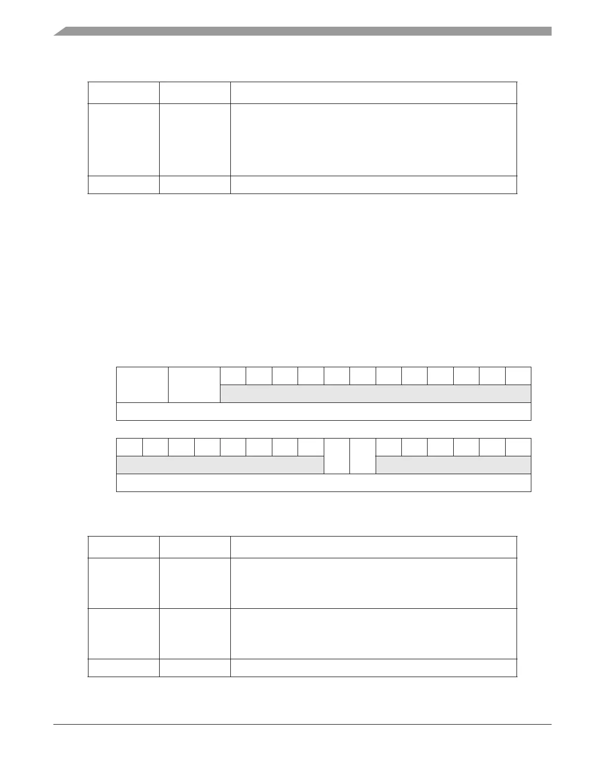
25.14.2.3 Data Trace Control Register (DTC)
The data trace control register controls whether DTM Messages are restricted to reads, writes or both for
a user programmable address range. There are two data trace channels controlled by the DTC for the
NXDM module.
22–20 DTE DTE - Data trace end control
000 Trigger disabled
001-100 Reserved
101 Use internal watchpoint #1 (BWA1 register)
110 Use internal watchpoint #2 (BWA2 register)
111 Reserved
19–0 – Reserved, read as 0.
31 30 29 28 27 26 25 24 23 22 21 20 19 18 17 16
RRWT1 RWT2 00000000
W
Reset0000000000000000
1514131211109876543210
R00000000RC1RC2000000
W
Reset0000000000000000
Figure 25-56. Data Trace Control Register (DTC)
Table 25-49. DTC Field Description
Bit Name Description
31–30 RWT1 Read/write trace 1
00 No trace messages generated
X1 Enable data read trace
1X Enable data write trace
29–28 RWT2 Read/write trace 2
00 No trace messages generated
X1 Enable data read trace
1X Enable data write trace
27–8 – Reserved, read as 0.
Table 25-48. WT Field Description (Continued)
Bit Name Description