MPC5553/MPC5554 Microcontroller Reference Manual, Rev. 5
Freescale Semiconductor 25-77
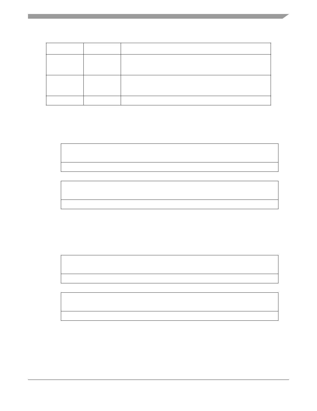
25.14.2.4 Data Trace Start Address Registers 1 and 2 (DTSA1 and DTSA2)
The data trace start address registers define the start addresses for each trace channel.
25.14.2.5 Data Trace End Address Registers 1 and 2 (DTEA1 and DTEA2)
The data trace end address registers define the end addresses for each trace channel.
Table 25-50 below illustrates the range that will be selected for data trace for various cases of DTSA being
less than, greater than, or equal to DTEA.
7 RC1 Range control 1
0 Condition trace on address within range (endpoints inclusive)
1 Condition trace on address outside of range (endpoints exclusive)
6 RC2 Range control 2
0 Condition trace on address within range (endpoints inclusive)
1 Condition trace on address outside of range (endpoints exclusive)
5–0 – Reserved, read as 0.
31 30 29 28 27 26 25 24 23 22 21 20 19 18 17 16
R DATA TRACE START ADDRESS
W
Reset0000000000000000
1514131211109876543210
R DATA TRACE START ADDRESS
W
Reset0000000000000000
Figure 25-57. Data Trace Start Address Registers (DTSA1, DTSA2)
31 30 29 28 27 26 25 24 23 22 21 20 19 18 17 16
R DATA TRACE END ADDRESS
W
Reset0000000000000000
1514131211109876543210
R DATA TRACE END ADDRESS
W
Reset0000000000000000
Figure 25-58. Data Trace Start Address Registers (DTEA1, DTEA2)
Table 25-49. DTC Field Description (Continued)
Bit Name Description