MPC5553/MPC5554 Microcontroller Reference Manual, Rev. 5
Freescale Semiconductor 25-85
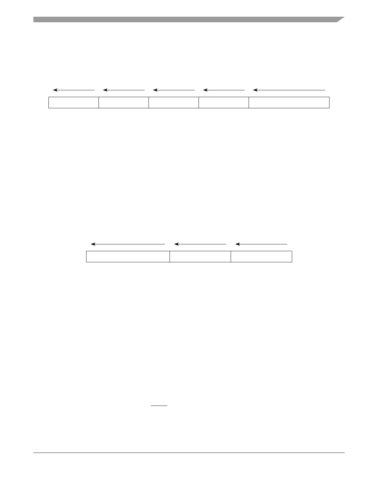
25.14.5.3.1 Data Write and Data Read Messages
The data write and data read messages contain the data write/read value and the address of the write/read
access, relative to the previous data trace message. Data write message and data read message information
is messaged out in the following format:
Figure 25-64. Data Write/Read Message Format
25.14.5.3.2 DTM Overflow Error Messages
An error message occurs when a new message cannot be queued due to the message queue being full. The
FIFO will discard incoming messages until it has completely emptied the queue. After it is emptied, an
error message will be queued. The error encoding will indicate which types of messages attempted to be
queued while the FIFO was being emptied.
If only a data trace message attempts to enter the queue while it is being emptied, the error message will
incorporate the data trace only error encoding (00010). If a watchpoint also attempts to be queued while
the fifo is being emptied, then the error message will incorporate error encoding (01000).
Error information is messaged out in the following format:
Figure 25-65. Error Message Format
25.14.5.3.3 Data Trace Synchronization Messages
A data trace write/read w/ sync. Message is messaged via the auxiliary port (provided data trace is enabled)
for the following conditions (see Table 25-58):
• Initial data trace message upon exit from system reset or whenever data trace is enabled will be a
synchronization message.
• Upon returning from a low power state, the first data trace message will be a synchronization
message.
• Upon returning from debug mode, the first data trace message will be a synchronization message.
• After occurrence of queue overrun (can be caused by any trace message), the first data trace
message will be a synchronization message.
• After the periodic data trace counter has expired indicating 255 without-sync data trace messages
have occurred since the last with-sync message occurred.
• Upon assertion of the Event In (EVTI) pin, the first data trace message will be a synchronization
message if the eic bits of the dc register have enabled this feature.
DATA
msb lsb
234
U-ADDR DSZ SRC
5
4 bits
1
TCODE (000101 or 000110)
3 bits1-32 bits1-64 bits 6 bits
Max length = 109 bits; Min length = 15 bits
ECODE (00010 / 01000)
msb lsb
12
SRC TCODE (001000)
3
6 bits4 bits5 bits
Fixed length = 15 bits