MPC5553/MPC5554 Microcontroller Reference Manual, Rev. 5
4-12 Freescale Semiconductor
4.4.3.4 PLLCFG[0:1] Pins
The role of PLLCFG pins in PLL configuration is explained in Section 11.1.4, “FMPLL Modes of
Operation.” Also refer to Chapter 2, “Signal Description” for information about the PLLCFG pins.
4.4.3.5 Reset Configuration Half Word
4.4.3.5.1 Reset Configuration Half Word Definition
The RCHW is read from either external memory or internal flash memory. If a valid RCHW is not found,
a CAN/SCI boot is initiated. The RCHW is a collection of control bits that specify a minimum MCU
configuration after reset and define the desired mode of operation of the BAM program. At reset the
RCHW provides a means to locate the boot code, determines if flash memory is programmed or erased,
enables or disables the watchdog timer, and if booting externally, sets the bus size. The user should refer
to the appropriate register given by the RCHW bit descriptions for a detailed description of each control
bit.
NOTE
Do not configure the RCHW to a 32-bit bus size for devices with only a
16-bit data bus.
If booting from internal flash or external memory, the user must insure that the RCHW is the correct value
for the desired configuration, and that it is located at the proper location in memory. The boot ID of the
RCHW must be read as 0x5A. BOOT_BLOCK_ADDRESS is explained in Section 16.3.2.2.5, “Reset
Configuration Halfword Read.”
1
0
Valid
Reserved The lowest address (0x00_0000) of an external
memory device, enabled by chip select CS0 using
either 16- or 32-bit data bus
Invalid Reserved Not applicable
1
Valid
Reserved The lowest address (0x0000_0000) of an external
memory device, enabled by chip select CS0 using
either 16- or 32-bit data bus.
Invalid Serial boot Not applicable
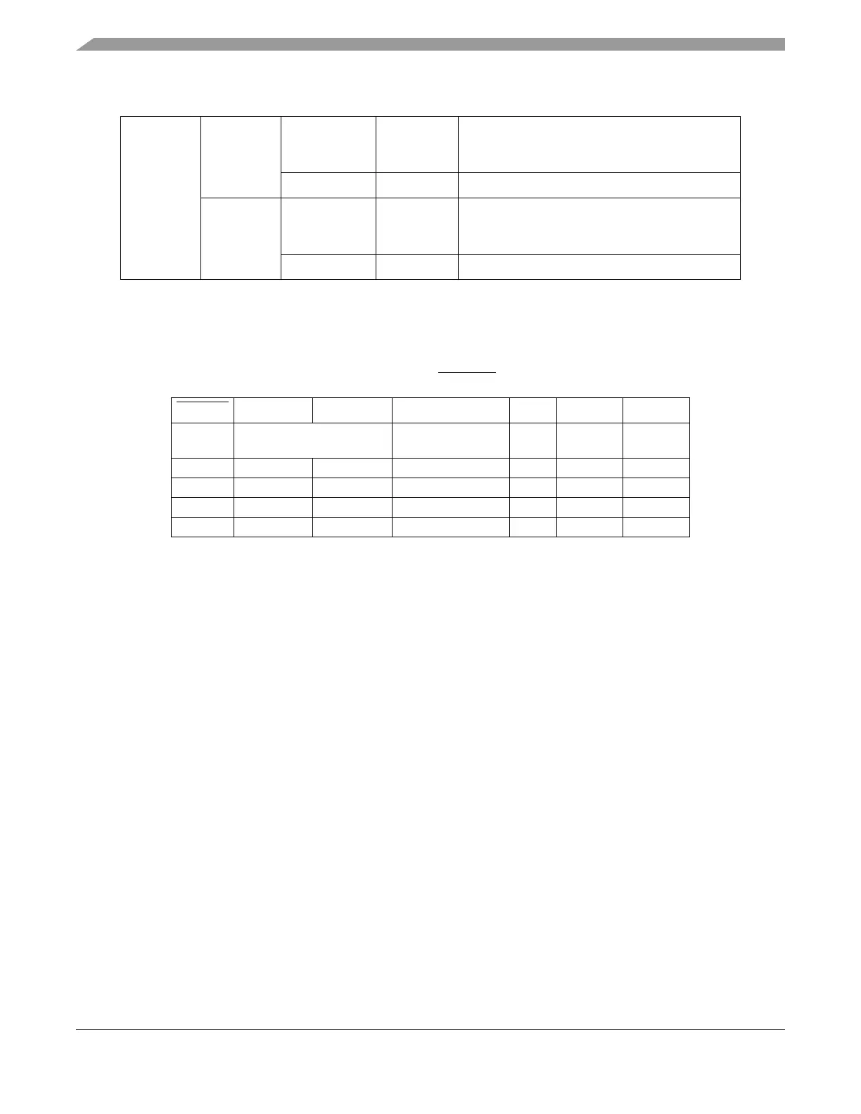
Table 4-8. PLLCFG[0:1] and RSTCFG in Configuration
RSTCFG PLLCFG0 PLLCFG1 Clock Mode MODE PLLSEL PLLREF
1 PLLCFG pins ignored Crystal reference
(default)
11 1
0 0 0 Bypass Mode 0 0 0
0 0 1 External reference 1 1 0
0 1 0 Crystal reference 1 1 1
0 1 1 1:1 Mode 1 0 0
Table 4-7. Boot Configuration in the 208 BGA (Continued)