MPC5553/MPC5554 Microcontroller Reference Manual, Rev. 5
16-4 Freescale Semiconductor
The MMU regions are mapped with logical address the same as physical address except for the external
bus interface (EBI). The logical EBI address space is mapped to physical addresses of the internal flash
memory. This allows a code, written to run from external memory, to be executed from internal flash
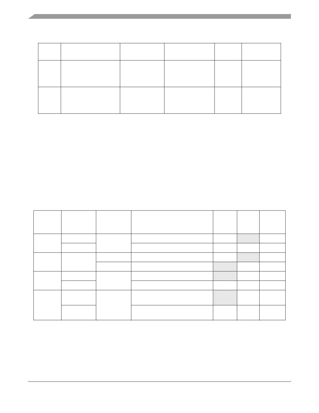
Then the BAM program reads the status of the two BOOTCFG pins from the reset status register
(SIU_RSR) and the appropriate boot sequence is started as shown in the Table 16-3.
Depending on the values stored in the censorship word and serial boot control word in the shadow row of
internal flash memory, the internal flash memory can be enabled or disabled, the Nexus port can be enabled
or disabled, the password received in serial boot mode is compared with a fixed public password or
compared to a user programmable password in the internal flash memory. The Table 16-3 summarizes all
these possibilities.
The censorship word is a 32-bit word of data stored in the shadow row of internal flash memory. This
memory location is read and interpreted by hardware as part of the boot process and is used in conjunction
with the BOOTCFG pins to enable/disable the internal flash memory and the Nexus interface. The
memory address of the censorship word is 0x00FF_FDE0. The censorship word consists of two fields:
3 Internal SRAM 0x4000_0000 0x4000_0000 256 Kbytes Cache inhibited
Not guarded
Big Endian
Global PID
4 Peripheral Bridge A 0xC3F0_0000 0xC3F0_0000 1 MB Cache inhibited
Not Guarded
1
Big Endian
Global PID
1
For future compatibility, configure peripheral bridge A as guarded.
Table 16-3. Boot Modes
BOOTCFG
[0:1]
Censorship
Control
0x00FF_FDE0
Serial Boot
Control
0x00FF_FDE2
Boot Mode Name
Internal
Flash
State
Nexus
State
Serial
Password
00 !0x55AA Don't care Internal—Censored Enabled
Disabled Flash
0x55AA Internal—Public Enabled Enabled Public
01 Don't care 0x55AA Serial—Flash Password Enabled
Disabled Flash
!0x55AA Serial—Public Password Disabled Enabled Public
10 !0x55AA Don't care External—No Arbitration—Censored Disabled Enabled Public
0x55AA External—No Arbitration—Public Enabled Enabled Public
11 !0x55AA Don't care External—External Arbitration
—Censored
Disabled Enabled Public
0x55AA External—External Arbitration
—Public
Enabled Enabled Public
Note: ’!’ = ’NOT’, meaning any value other than the value specified. Values 0x0000 and 0xFFFF should not be used.
Table 16-2. MMU Configuration for Internal Flash Boot
TLB
Entry
Region
Logical Base
Address
Physical Base
Address
Size Attributes