MPC5553/MPC5554 Microcontroller Reference Manual, Rev. 5
Freescale Semiconductor 17-23
either eTPU engine can be exported to the other eTPU engine and to the eMIOS module, which is only a
STAC client. There are restrictions on engine export/import targets: one engine cannot export from or
import to itself, nor can it import time base and/or angle count if in angle mode.
The MPC5553/MPC5554 STAC server identification assignment is shown in Table 17-13. The time slot
assignment is fixed, so only time bases running at system clock 4 or slower can be integrally exported.
The STAC client submodule runs with the system clock, and its time slot timing is synchronized with the
eTPU timing on reset. The time slot sequence is 0-1-2-3, such that they are alternated between engines 1
and 2.
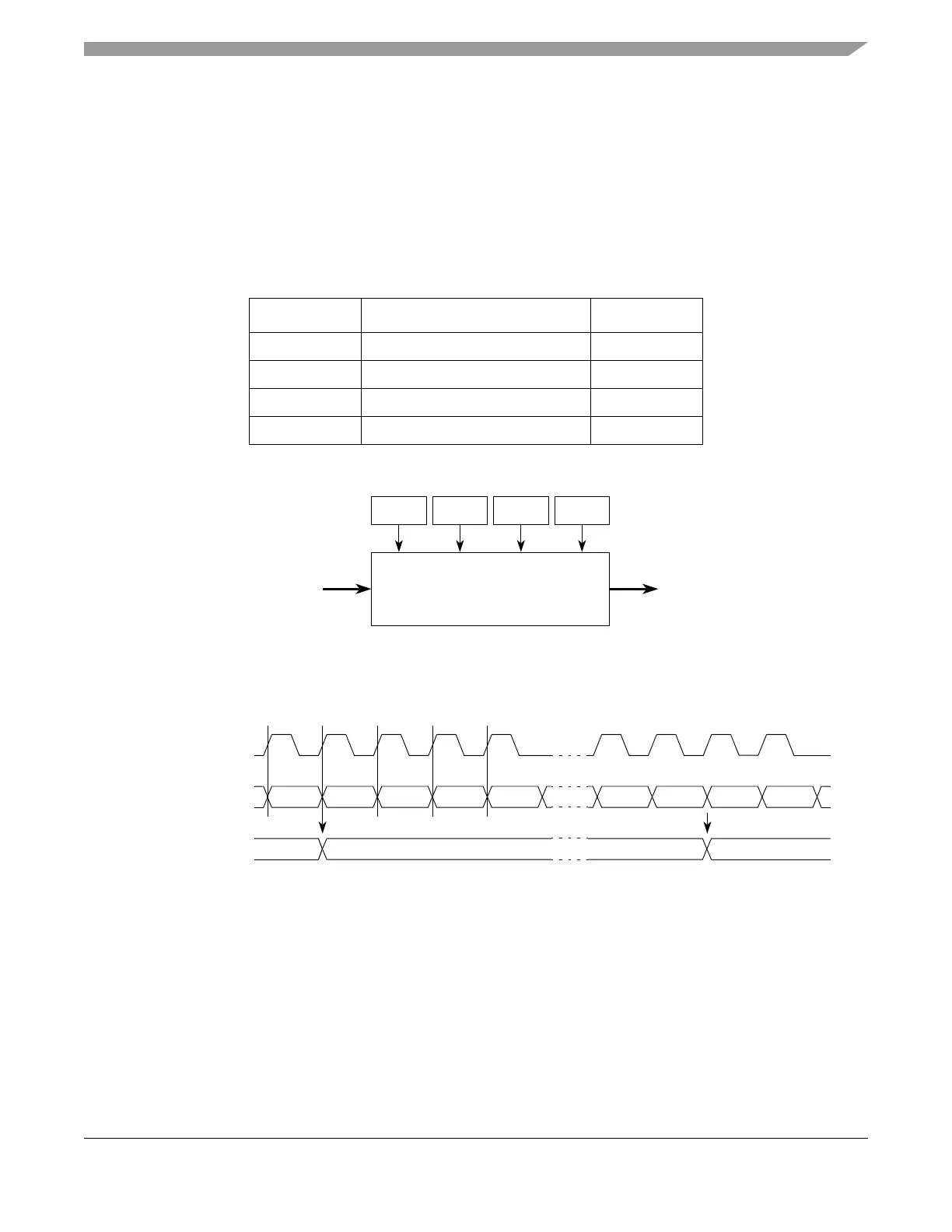
Figure 17-10 provides a block diagram for the STAC client submodule.
Figure 17-10. STAC Client Submodule Block Diagram
Bits SRV[0:3] in register EMIOS_MCR, selects the desired time slot of the STAC bus to be output.
Figure 17-11 shows a timing diagram for the STAC client submodule.
Figure 17-11. Timing Diagram for the STAC Bus and
STAC Client Submodule Output
Every time the selected time slot changes, the STAC Client Submodule output is updated.
17.4.2.1 Effect of Freeze on the STAC Client Submodule
When the FRZ bit in the EMIOS_MCR is set and the module is in debug mode, the operation of the STAC
client submodule is not affected; that is, there is no freeze function in this submodule.
Table 17-13. STAC Client Submodule Server Slot Assignment
Engine Time Base Server ID
1 TCR1 0
1 TCR2 2
2 TCR1 1
2 TCR2 3
SRV3 SRV2 SRV1 SRV0
STAC Bus Time Base
STAC Client Submodule
(24-bit Wide) Output
Time Slot Selector Bits
TS[02]
STAC Bus
(Submodule Input)
TS[00] TS[01] TS[02]
Time Base
(Submodule Output)
TS[01] TS[01]xx
Note: In this case, SRV bits were set to capture TS[01].
TS[03] TS[00] TS[03] TS[00] TS[01]
System Clock