MPC5553/MPC5554 Microcontroller Reference Manual, Rev. 5
Freescale Semiconductor 17-25
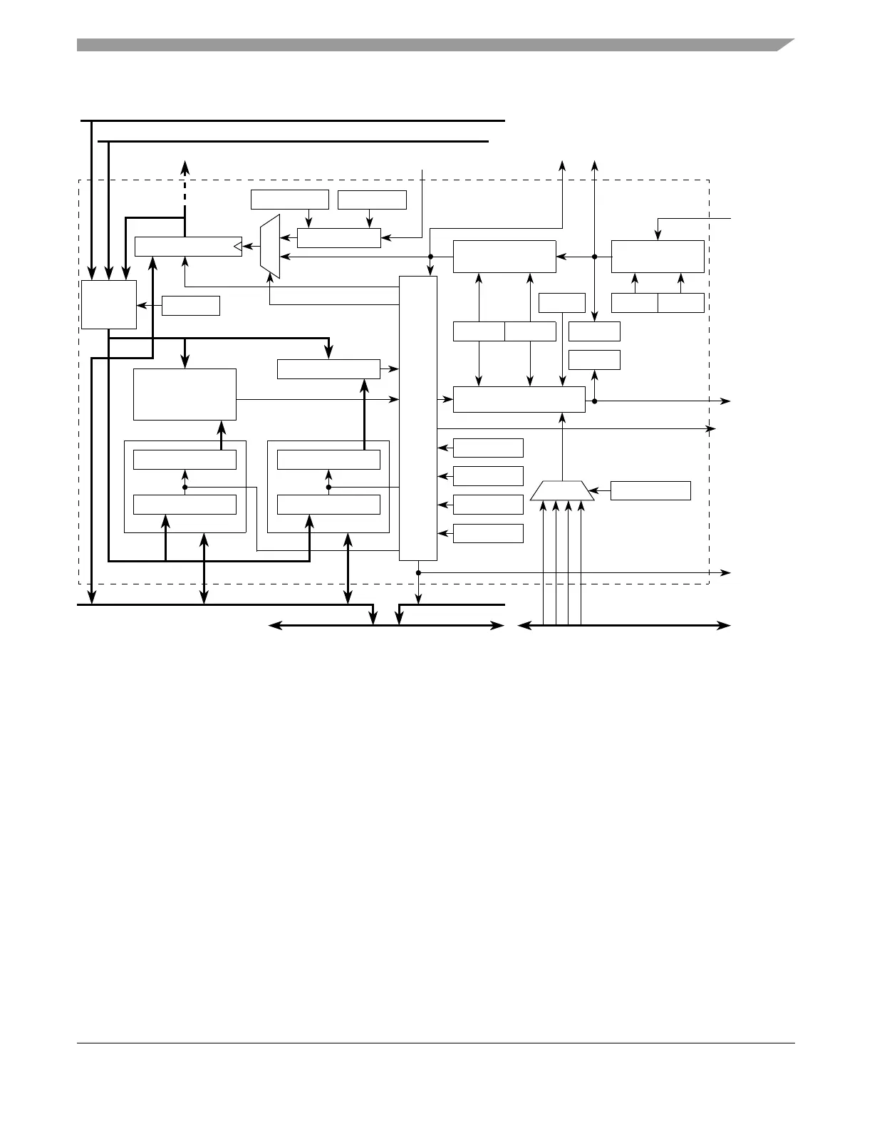
Figure 17-12. Unified Channel Block Diagram
17.4.4.1 Programmable Input Filter (PIF)
The PIF ensures that only valid input pin transitions are received by the unified channel edge detector. A
block diagram of the PIF is shown in Figure 17-13.
The PIF is a 5-bit programmable up counter that is incremented by the selected clock source, according to
bits IF[0:3] in EMIOS_CCRn. The clock source is selected by the EMIOS_CCRn[FCK] bit.
Programmable
Filter
FSM
IF[0:3]
UCIN
UCOUT
ODIS
EDSELEDPOL
Edge Detect
Output Flip-Flop
FCK
Comparator A
(with Zero
Prescaler
UCPRE[0:1]
BSL[0:1]
Detection)
Comparator B
Register CADR
ENEN
FORCMB
RWCB RQB
See Note 2
Internal Counter Clock
See Note 1
Counter Bus B, C, or D
Counter Bus A
FORCMA
MODE[0:6]
UPDATE
Output Disable
Control Bus
ODISSL[0:1]
EMIOS_Flag_Outn
EMIOS_UCn
EMIOSn
EMIOSn
Internal Bus
Unified Channel
Counter
Bus
Select
Internal Counter
Register A1
Register A2
Register B1
Register B2
Notes:
1. Counter bus A can be driven by either the STAC bus or channel 23. Refer to EMIOS_MCR[ETB].
2. Goes to the finite state machine of the UC[n-1]. These signals are used for QDEC mode.
FLAG
Register CBDR
Channel 0 drives counter bus B, channel 8 drives counter bus C and channel 16 drives counter bus D.
Counter bus B can be selected as the counter for channels 0-7, counter bus C for channels 8-15,
and counter bus D for channels 16-23. Refer to Figure 16-1 and EMIOS_CCRn[BS].
UCPREN