MPC5553/MPC5554 Microcontroller Reference Manual, Rev. 5
17-26 Freescale Semiconductor
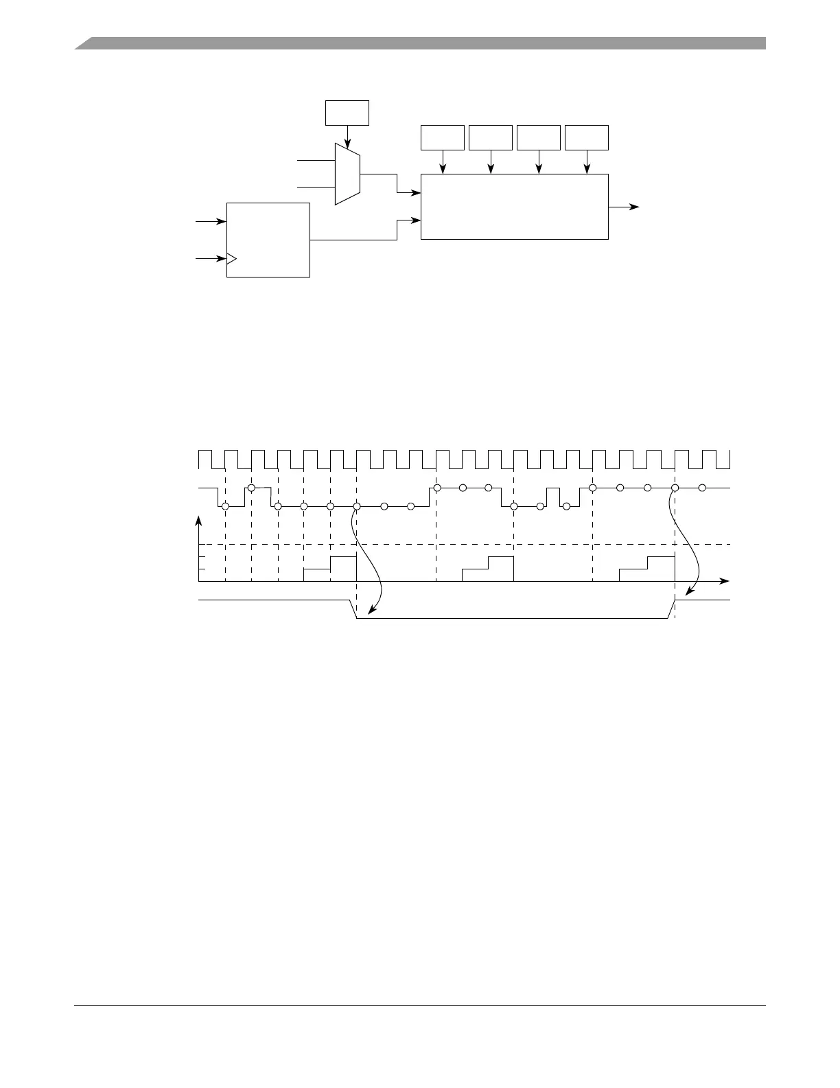
Figure 17-13. Programmable Input Filter Submodule Diagram
The input signal is synchronized by the system clock. When a state change occurs in this signal, the 5-bit
counter starts counting up. As long as the new state is stable on the pin, the counter continues incrementing.
If a counter overflows occurs, the new pin value is validated. In this case, it is transmitted as a pulse edge
to the edge detector. If the opposite edge appears on the pin before validation (overflow), the counter is
reset. At the next synchronized pin transition, the counter starts counting again. Any pulse that is shorter
than a full range of the masked counter is regarded as a glitch, and it is not passed on to the edge detector.
A timing diagram of the input filter is shown in Figure 17-14.
Figure 17-14. Programmable Input Filter Example
17.4.4.2 Clock Prescaler (CP)
A unified channel has a clock prescaler (CP) that divides the global clock prescaler (refer to Section 17.4.3,
“Global Clock Prescaler Submodule (GCP)”) output signal to generate a clock enable for the internal
counter of the unified channel. It is a programmable 2-bit down counter. The global clock prescaler
submodule (GCP) output signal is prescaled by the value defined in Table 17-10 according to the
UCPRE[0:1] bits in the EMIOS_CCRn. The output is clocked every time the counter reaches zero.
Counting is enabled by setting the UCPREN bit in the EMIOS_CCRn. The counter can be stopped at any
time by clearing this bit, thereby stopping the internal counter in the unified channel.
17.4.4.3 Effect of Freeze on the Unified Channel
When in debug mode and the EMIOS_MCR[FRZ] bit and the EMIOS_CCRn[FREN] bit are both set, the
internal counter and the unified channel’s capture and compare functions are halted. The UC is frozen in
its current state.
During freeze, all registers are accessible. When the unified channel is operating in an output mode, the
force match functions remain available, allowing the software to force the output to the desired level.
Synchronizer
IF3
CLK
IF2 IF1 IF0
5-bit Up Counter
FCK
Prescaled Clock
EMIOSn
Clock
System Clock
Filter Out
Selected Clock
5-bit Counter
IF = 0b0011
Filter Out
EMIOSn
Time