MPC5553/MPC5554 Microcontroller Reference Manual, Rev. 5
Freescale Semiconductor 17-37
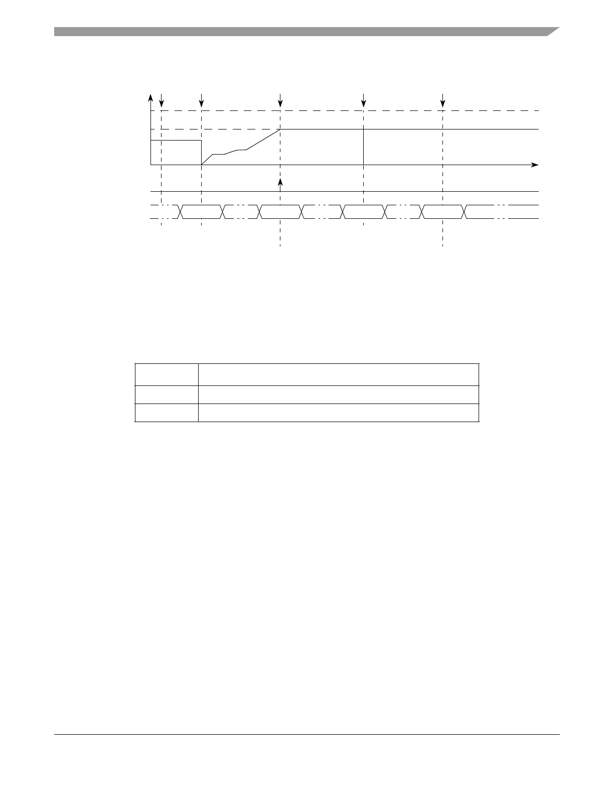
Figure 17-25. Pulse/Edge Counting Single-Shot Mode Example
17.4.4.4.9 Quadrature Decode Mode (QDEC)
Quadrature decode mode uses UCn operating in QDEC mode and the programmable input filter (PIF)
from UC[n-1]. Note that UC[n-1] can be configured, at the same time, to an operation mode that does not
use I/O pins, such as MC mode (modulus counter). The connection among the UCs is circular; that is, when
UC0 is running in QDEC mode, the programmable input filter from UC23 is being used.
This mode generates a FLAG every time the internal counter matches A1 register. The internal counter is
automatically selected and is not cleared when entering this mode.
MODE[6] bit selects which type of encoder will be used: count and direction encoder or phase_A and
phase_B encoders.
When operating with count and direction encoder (MODE[6] cleared), UCn input pin must be connected
to the direction signal and UC[n-1] input pin must be connected to the count signal of the quadrature
encoder. UCn EDPOL bit selects count direction according to direction signal and UC[n-1] EDPOL bit
selects if the internal counter is clocked by the rising or falling edge of the count signal.
When operating with phase_A and phase_B encoder (MODE[6] set), UCn input pin must be connected to
the phase_A signal and UC[n-1] input pin must be connected to the phase_B signal of the quadrature
encoder. EDPOL bit selects the count direction according to the phase difference between phase_A and
phase_B signals.
Figure 17-26 and Figure 17-27 show two unified channels configured to quadrature decode mode for
count and direction encoder and phase_A and phase_B encoders, respectively.
Table 17-22. Mode of Operation: QDEC Mode
MODE[0:6] Unified Channel Mode of Operation
0b0001100 Quadrature decode (for count and direction encoders type)
0b0001101 Quadrature decode (for phase_A and phase_B encoders type)
Selected
Counter Bus
0x000090 0x000090
B1 Value
2
0x000090
0x000303 0x0003030x000303
Amount of
EMIOS_CCNTRn
FLAG
Set Event
MODE[6] = 1
A1 Match B1 Match B1 Match
A1 Value
1
Notes:
1
Reading EMIOS_CADRn returns the value of A1.
2
Reading EMIOS_CBDRn returns the value of B1.
Time
0x000000
Events
Detected
A1 Match
A1 & B1
Write
0x000090 0x000303 0x000090 0x000303