MPC5553/MPC5554 Microcontroller Reference Manual, Rev. 5
20-48 Freescale Semiconductor
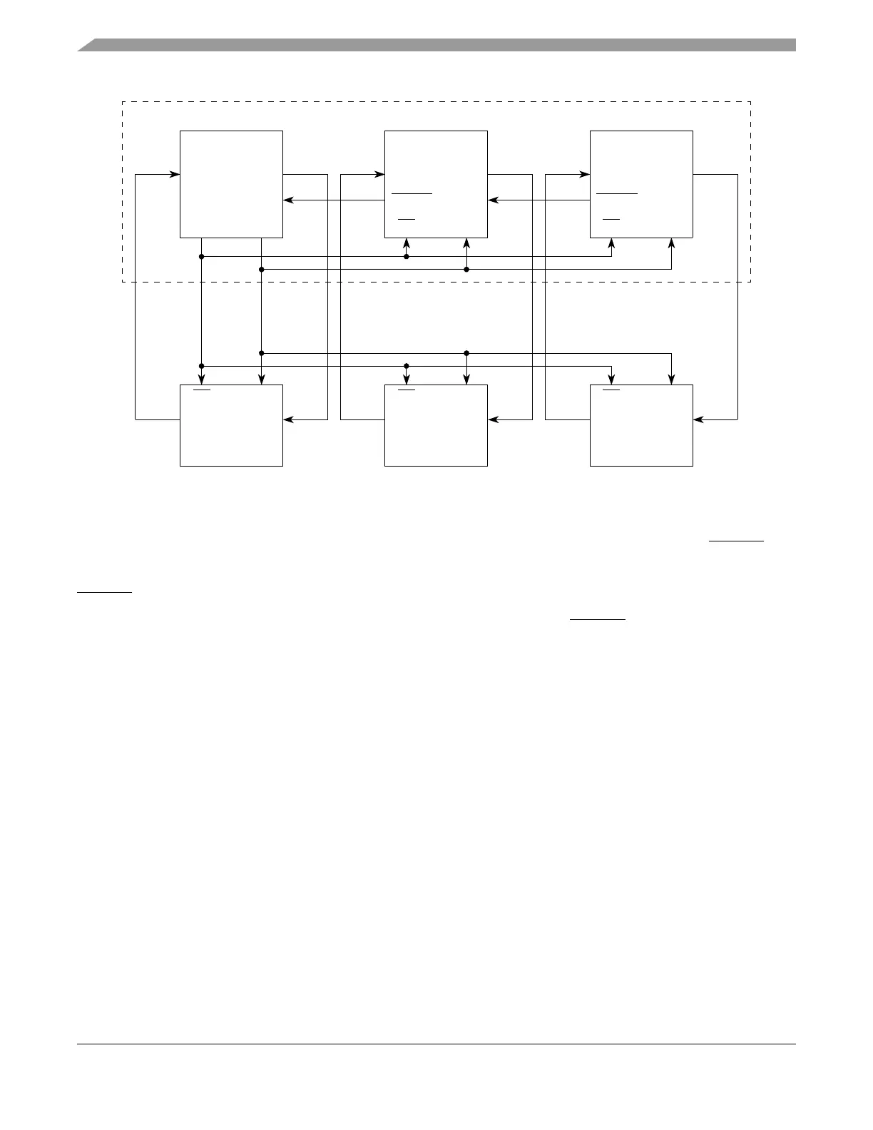
Figure 20-28. Example of Parallel Chaining of DSPIs in the MPC5553
In the parallel chaining example, the SOUT and SIN of the three DSPIs connect to separate external SPI
devices. All internal and external SPI modules share PCS and SCK signals. In the MPC5554, DSPI_A
controls and initiates all transfers, but the DSPI slaves each have a trigger output signal MTRIG that
indicates to DSPI_A that a trigger condition has occurred in the DSPI slaves. In the MPC5553, it is
DSPI_B that controls and initiates all transfers, but the DSPI slaves each have a trigger output signal
MTRIG that indicates to DSPI_B that a trigger condition has occurred in the DSPI slaves.
When the slave DSPI has a change in data to be serialized, it asserts the MTRIG signal that propagates to
DSPI_A (MPC5554)/DSPI_B (MPC5553) which initiates the transfer. In the MPC5554, DSPI_B
propagates trigger signals from DSPI_C to DSPI_A. In the MPC5554, DSPI_C propagates trigger signals
from DSPI_D to DSPI_B.
The MTOCNT field in the DSPIx_DSICR must be written with the number of bits to be transferred. In
parallel chaining the number written to MTOCNT must match the FMSZ field in the selected
DSPIx_CTAR.
20.4.4.7.3 Serial Chaining
Serial chaining allows transfers of DSI frames consisting of concatenated bits from multiple DSPIs. The
concatenated frames can be from 8 to 64 bits long. Figures 20-29 and 20-30 show an example of how the
modules can be connected in the MPC5554/MPC5553, respectively.
SOUT
HT
SCK
SIN
MTRIG
SS
MPC5553
DSPI_B
SOUT
HT
SCK
SIN
PCS0
SIN_B
PCS_B0
SCK_B
SOUT_B
SIN_C
(Master)
DSPI_C
(Slave)
SOUT
SCK
SIN
MTRIG
SS
DSPI_D
(Slave)
SOUT_C
SIN_D
SOUT_D
SCKSS
SIN
Slave Device
SPI
SOUT
SCKSS
SIN
Slave Device
SPI
SOUT
SCKSS
SIN
Slave Device
SPI
SOUT