MPC5553/MPC5554 Microcontroller Reference Manual, Rev. 5
Freescale Semiconductor 21-7
The baud rate generator is disabled when SBR0–SBR12 = 0x0.
Normally the baud rate should be written with a single write. If 8-bit writes
are used, writing to ESCIx_CR1[0–7] has no effect without writing to
ESCIx_CR1[8–15], because writing to ESCIx_CR1[0–7] puts the data in a
temporary location until ESCIx_CR1[8–15] is written to.
During reception, when parity is enabled, the received parity bit will appear
in the data register.
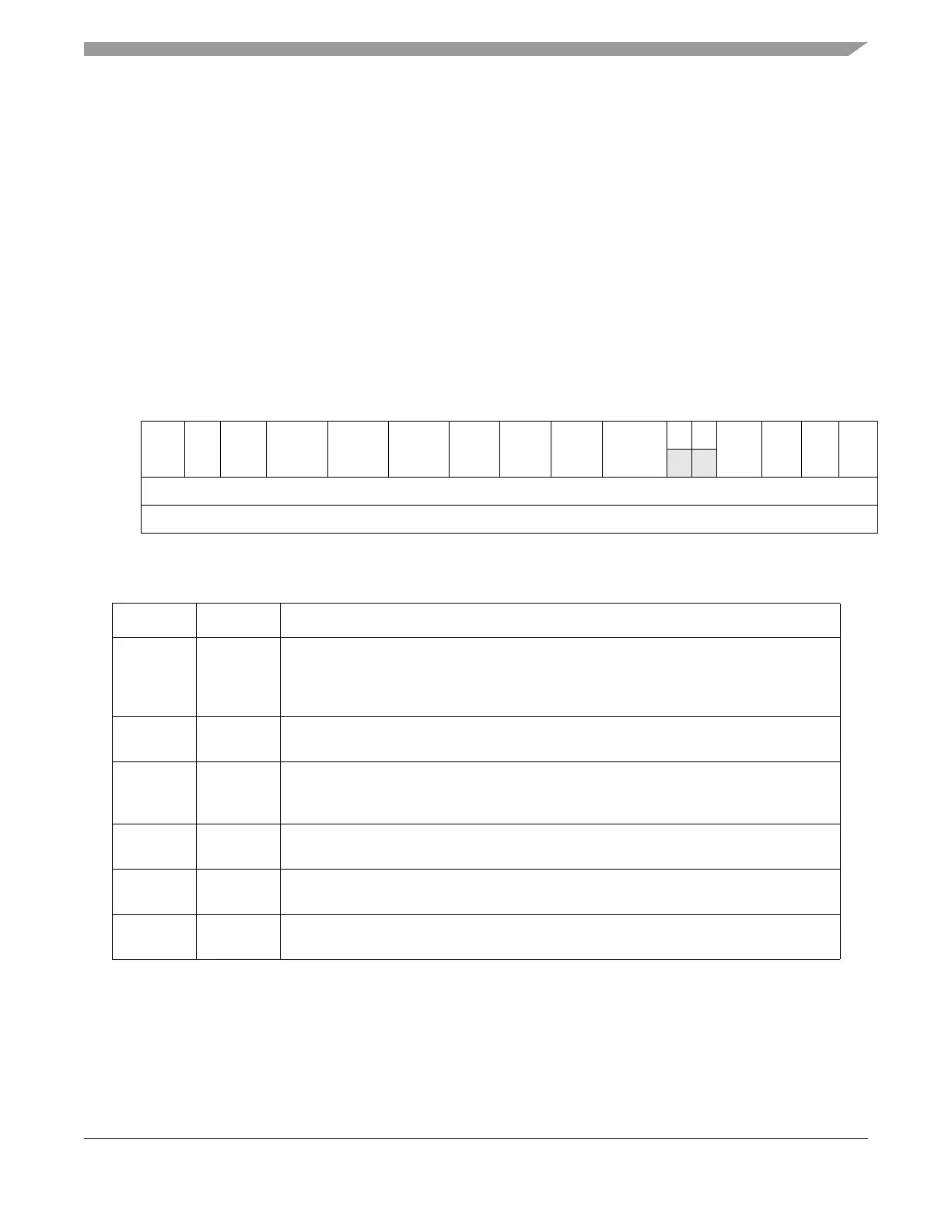
21.3.3.2 eSCI Control Register 2 (ESCIx_CR2)
NOTE
DMA requests are negated when in module disable mode.
0 1 2 3 4 5 6 7 8 9 10 11 12 13 14 15
R MDIS FBR BSTP IEBERR RXDMA TXDMA BRK13 0 BESM
13
SBSTP 0 0 ORIE NFIE FEIE PFIE
W
Reset 0 0 1 0 0 0 0 0 0 0 0 0 0 0 0 0
Reg Addr Base + 0x004
Figure 21-3. eSCI Control Register 2 (ESCIx_CR2)
Table 21-4. ESCIx_CR2 Field Description
Bits Name Description
0 MDIS Module disable. By default the module is enabled, but can be disabled by writing a 1 to this
bit. DMA requests are negated if the device is in module disable mode.
0 Module enabled
1 Module disabled
1 FBR Fast bit error detection. Handles bit error detection on a per bit basis. If this is not enabled,
bit errors will be detected on a per byte basis.
2 BSTP Bit error/physical bus error stop. Causes DMA TX requests to be suppressed, as long as
the bit error and physical bus error flags are not cleared. This stops further DMA writes,
which would otherwise cause data bytes to be interpreted as LIN header information.
3 IEBERR Enable bit error interrupt. Generates an interrupt, when a LIN bit error is detected. For a
list of interrupt enables and flags, see Tabl e 21 -2 1.
4 RXDMA Activate RX DMA channel. If this bit is enabled and the eSCI has received data, it will raise
a DMA RX request.
5 TXDMA Activate TX DMA channel. Whenever the eSCI is able to transmit data, it will raise a DMA
TX request.