MPC5553/MPC5554 Microcontroller Reference Manual, Rev. 5
21-16 Freescale Semiconductor
Table 21-8. ESCIx_LTR First Byte Field Description
Bits Name Description
0–1 Pn Parity bit n. When parity generation is enabled (ESCIx_LCR[PRTY] = 1), the parity bits are
generated automatically. Otherwise they must be provided in this field.
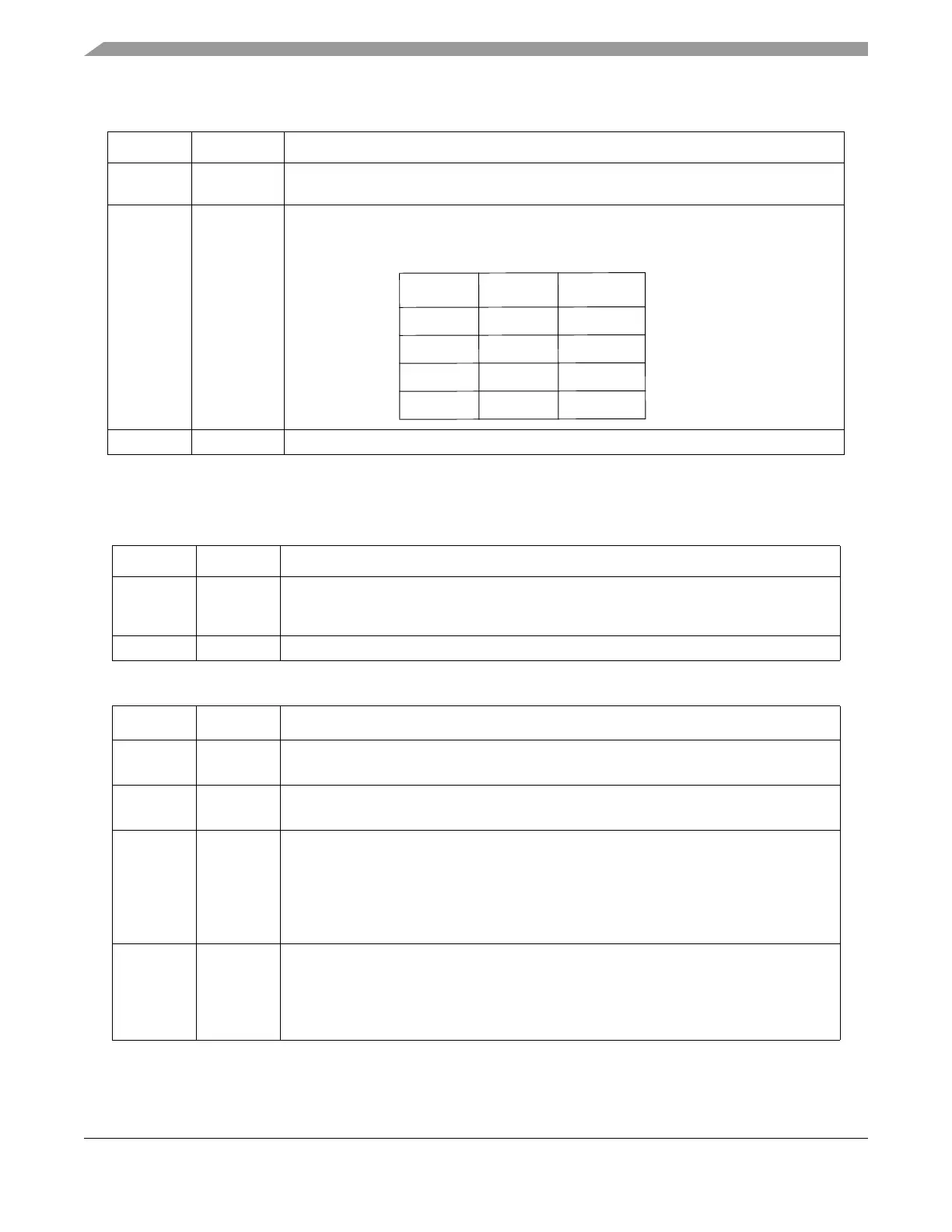
2–7 IDn
1
1
The values 3C, 3D, 3E and 3F of the ID-field (ID0-5) indicate command and extended frames.Refer to LIN Specification
Package Revision 2.0.
Header bit n. The LIN address, for LIN 1.x standard frames the length bits must be set
appropriately (see the table below), extended frames are recognized by their specific
patterns.
8–31 — Reserved.
Table 21-9. ESCIx_LTR Second Byte Field Descriptions
Bits Name Description
0–7 Ln Length bit n. Defines the length of the frame (0 to 255 data bytes). This information is
needed by the LIN state machine in order to insert the checksum or CRC pattern as
required. LIN 1.x slaves will only accept frames with 2, 4, or 8 data bytes.
8–31 — Reserved.
Table 21-10. ESCIx_LTR Third Byte Field Descriptions
Bits Name Description
0 HDCHK Header checksum enable. Include the header fields into the mod 256 checksum of the
standard frames.
1 CSUM Checksum enable. Append a checksum byte to the end of a TX frame. Verify the checksum
byte of a RX frame.
2 CRC CRC enable. Append two CRC bytes to the end of a TX frame. Verify the two CRC bytes
of a RX frame are correct. If both CSUM and CRC bits are set, the LIN FSM will first append
the CRC bytes, then the checksum byte, and will expect them in this order, as well. If
HDCHK is set, the CRC calculation will include header and data bytes, otherwise just the
data bytes. CRC bytes are not part of the LIN standard; they are normal data bytes and
belong to a higher-level protocol.
3 TX Transmit direction. Indicates a TX frame; that is, the eSCI will transmit data to a slave.
Otherwise, an RX frame is assumed, and the eSCI only transmits the header. The data
bytes are received from the slave.
0 RX frame
1 TX frame
I
D
5
I
D
4
d
a
t
a
b
y
t
e
s
0
0
2
0
1
2
1
0
4
1
1
8