OPERATOR’S STATION
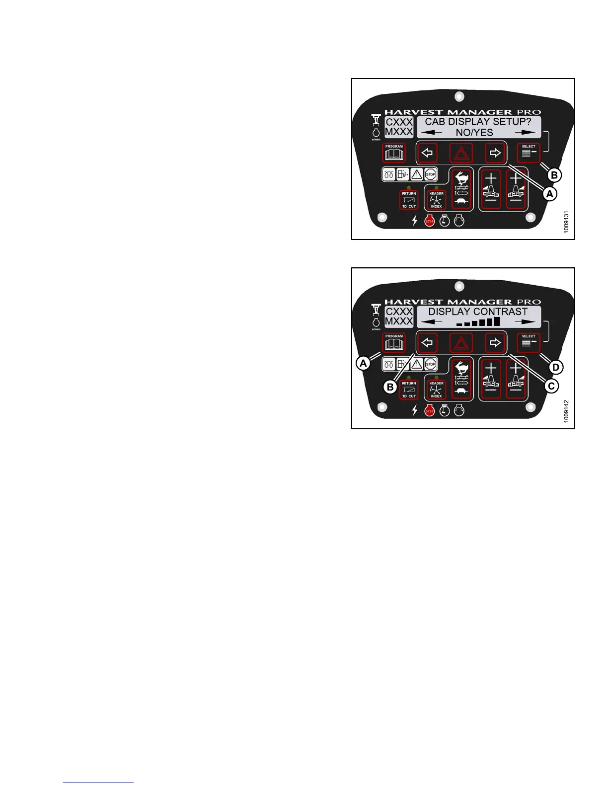
3. Press SELECT (B) until CAB DISPLAY SETUP? is
displayed on the upper line.
• NO/YES is displayed on the lower line .
4. Press right (A) arrow to select YES. Press SELECT (B).
• DISPLAY LANGUAGE? is displayed on the
upper line.
Figure 3.83
: M155 Cab Display Setup
5. Press SELECT (D) until D ISPLAY CONTRAST is
displayed on the upper line.
• Default se tting i s displayed on the lower line.
6. Press left (B) or right (C) arrows to adjust
display contrast.
7. Press P ROGRAM (A ) to exit Prog r am ming Mode or
press SELECT (D) to proceed to next CAB DISPLAY
SETUP? action.
Figure 3.84: M155 Display Contrast
3.19.7 Calibrating the Header S en sors
Sensor calibration programs the windrower control module (WCM) with settings for the attached header.
Calibrating the Header Height Sensor
NOTE:
•Thehe
ader MUST be attached to the windrower to perform this procedure. The cab display module (CDM)
auto
matically adjusts its programming for each header. For more information, refer to 4.5 Attaching and
Deta
ching Headers, page 213.
•Thee
ngine MUST be running to perform this procedure.
147649 95 Revision A