OPERATION
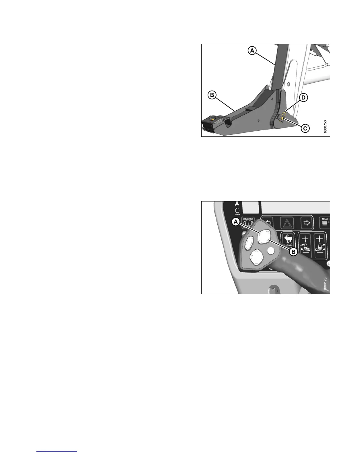
2. Position boot (B) onto lift linkage (A) and reinstall
pin (C ). Pin may be installed from either side of boot.
3. Secure pin (C) with hairpin (D).
4. Repeat for opposite side.
Figure 4.282: Header Boot
4.6.3 H ead er Position
Refer to 4.
4 Operating with a Header, page 193 for procedures for co ntrolling header height, heade r tilt, and float.
4.6.4 Adju
sting the Reel Fore-Aft Position
The reel f
ore-aft position can be hydraulically adjusted
with the o
ptional reel position system and is controlled with
multi-fu
nction switches on the ground speed lever (GSL).
Press an
d hold the switch for the desired FORWARD (A)
or AFT (B
) movement of the reel.
NOTE:
The switches also control adjustments to the optional
double windrow attachment (DWA) conveyor and
can be activated when programming the cab display
module (CDM).
Figure 4.283: Ground Speed Lever (GSL)
147649 281 Revision A