OPERATION
CAUTION
Check to be sure all bystanders have cleared the area.
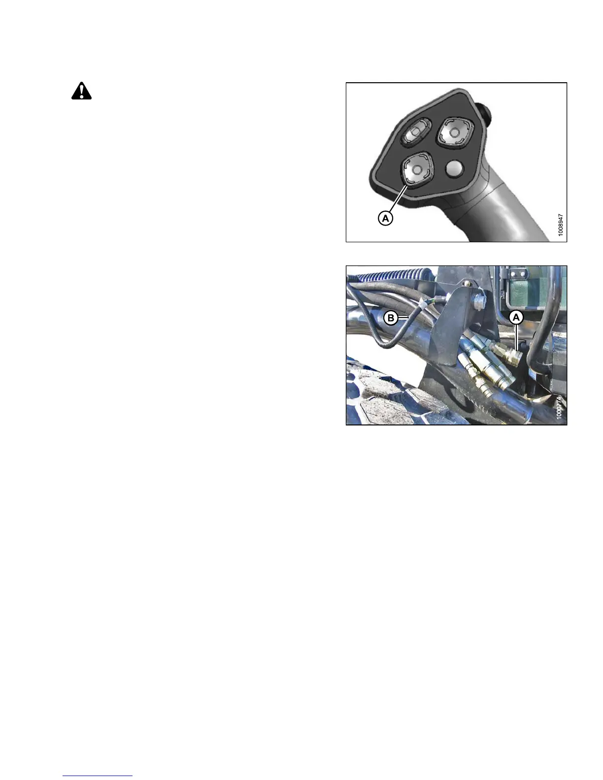
15. Start the engine and activate the header down
switch (A) on the GSL t o f ully lo wer the header.
16. Stop engine and remove key from ignition.
Figure 4.257: GSL
17. Connect he
ader drive hoses (A) and electrical
harness (B
) to header. Refer to the rotary disc header
operator
’s manual.
Figure 4.258: H e ader Dri ve Ho ses and Harn es s
4.5.6 D etaching an R-Series Header
Refer to the procedure that is appropriate for the center-link installed on the windrower:
• Detaching an R-Series Header: Hydraulic Center-Link, page 272
• Detaching an R-Series Header: Mechanical Center-Link, page 275
147649
2
71
Revision A