OPERATOR’S STATION
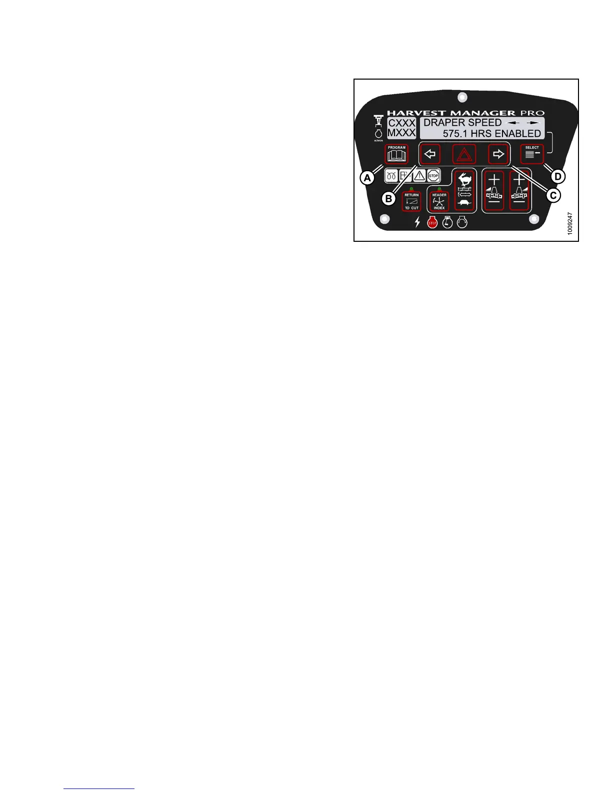
6. Press left (B) or right (C) arrow to cycle between control
switch lock outs. The displayed control switches a re
as follows:
• HEADER TILT
• HEADER FLOAT
• REEL FORE/AFT
• DRAPER SPEED
• AUGER SPEED
• KNIFE SPEED
• DISK SPEED
• REEL SPEED
NOTE:
Not all control locks apply to every header.
7. Press SELECT.
• EXIT VIEW LOC KOUTS? is displayed on the
upper line.
• NO/YES is displayed on the lower line .
8. Press r ight to select YES.
9. Press PRO GRAM to exit Prog ramming Mode or
press SELECT to proceed to next WINDROWER
SETUP action.
Figure 3.15
7: M155 Control Locks
3.19.11 Troubl
eshooting Windrower Problems
Displaying th
e Windrower and Engine Error Codes
NOTE:
The header MUST be attached to the windrower to perform this procedure. The cab display m odule (CDM)
automatically adjusts its programming for each header. For more information, refer to 4.5 Attaching and
Detaching Headers, page 213.
147649 129 Revision A