OPERATION
6. Select a second preset with the FLOAT PRESET 2
SWITCH (C).
7. Repeat Steps 1., page 198 and 2., p age 198 to set
the float.
8. Select a third preset with the FLOAT PRESET 3
SWITCH (D).
9. Repeat steps 1., page 198 and 2., page 198 to se t
the float.
10. Operate windrower.
NOTE:
For draper headers with the deck shift option, the
float can be preprogrammed to compensate for
weight distribution when the decks are shifted. Refer
to Setting Float Options with Deck Shift, page 291.
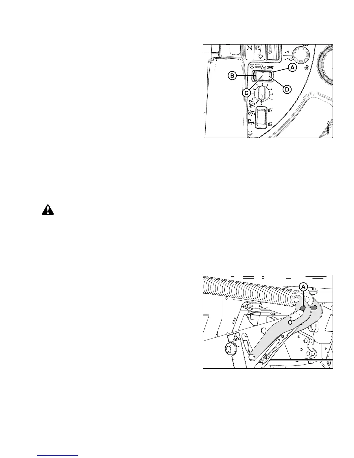
Figure 4.82: Float Preset Switch
4.4.3 L evelling the Header
The windrower lin
kages are factory-set to provide the proper level for the header and should not normally
require adjustme
nt.
DANGER
To avoid bodily injury or death from unexpected startup of the machine, always stop the engine and remove
the key from the ignition before leaving the operator ’s seat for any reason.
If the head er is not level, check the w indrower tire pressu res before adjusting the levelling linka ges.
NOTE:
The float springs are NOT used to level the header.
To level the header, follow these steps:
1. Place float pins in locked out location (A).
Figure 4.83: Float Pins – Disengaged
147649 199 Revision A