OPERATION
Hydraulic Link with Optional Self-Alignment Kit
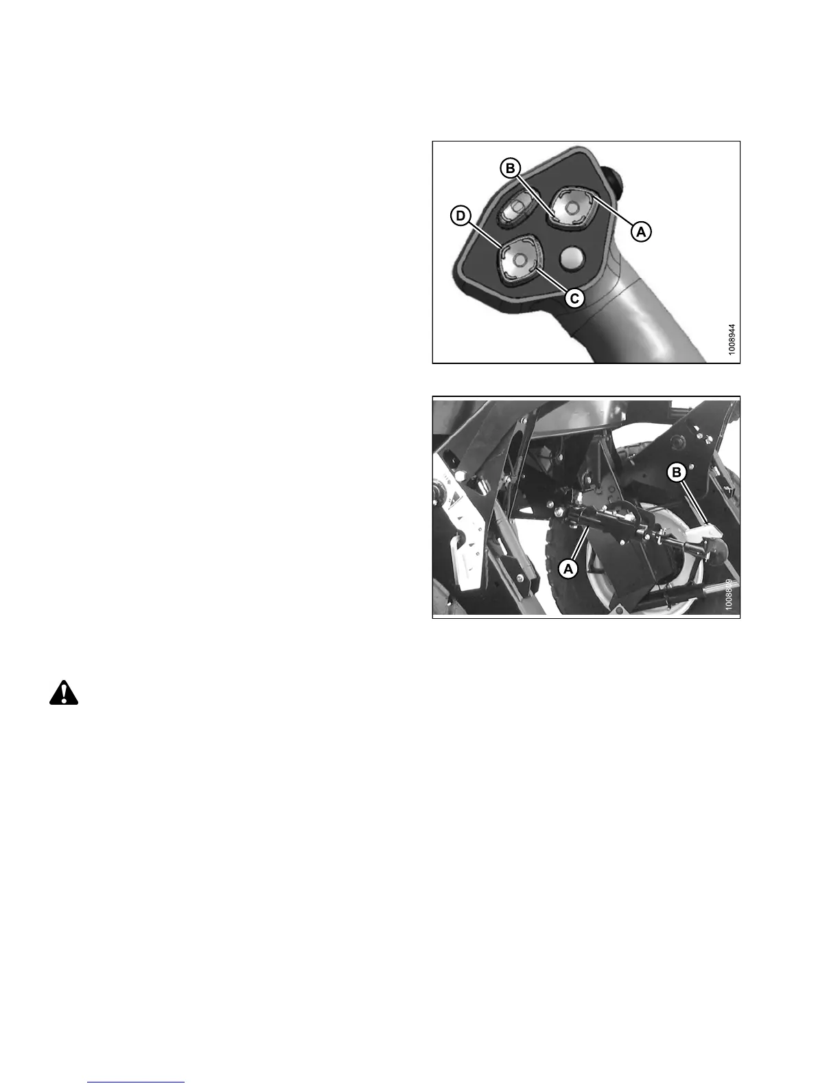
1. Adjust positio n o f the cente r-link cylinder with the reel
up (A), reel down (B), header tilt up (C), and header tilt
down (D) switc he s on the ground speed lever (GSL) to
position the hook above the header attachment pin.
IMPORTANT:
Hook release
must be down to enable self-locking
mechanism. I
f the release is open (up), manually
push it down a
fter hook engages header pin.
Figure 4.1
70: GSL
2. Lower center-link (A) onto the header with reel down
switch until it locks into position (hook release [B]
is down).
3. Check that center-link is locked onto header by
pressing the reel up switch on the G SL.
Figure
4.171: Hydraulic Center-Link
Attach
ing an A-Series Header: Hydraulic Center-Link without Self-Alignment
DANGER
To avoid bodily injury or death from unexpected startup of the machine, always stop the engine and remove
the key from the ignition before leaving the operator’s seat for any reason.
147649 238 Revision A