OPERATOR’S STATION
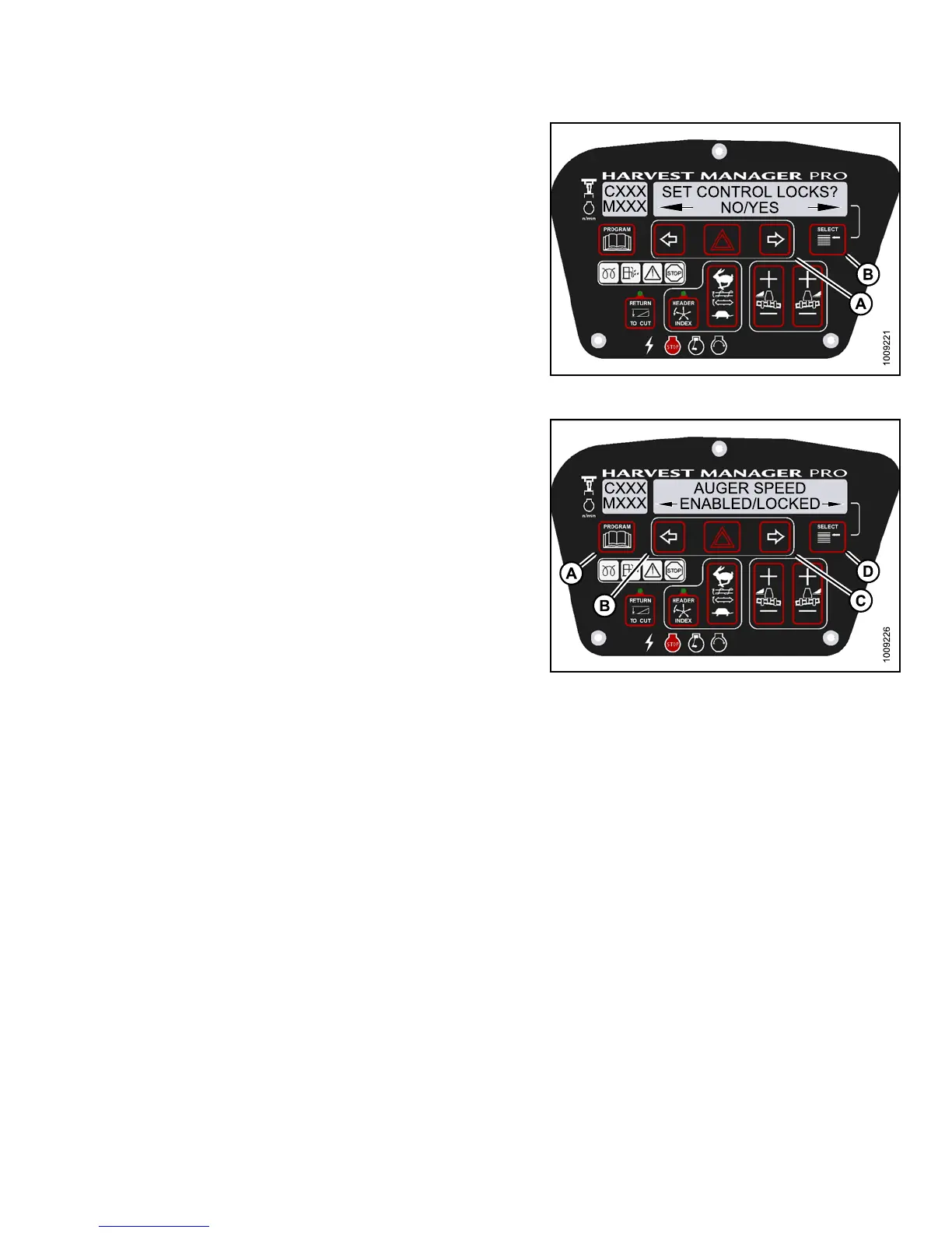
4. Press SELECT (B) until SET CONTROL LOCK S? is
displayed on the upper line.
• NO/YES is displayed on the lower line .
5. Press right (A) arrow to select YES. Press SELECT (B).
Figure 3.14
4: M155 Control Locks
6. Press SELECT (D) until AUGER SPEED is displayed
on the upper line.
• ENABLED/LOC KED is displayed on the lower line.
7. Press left (B) arrow to enable AUGER SPEED
control switch.
Press right (C) arrow to lock AUGER SPEE D
control switch.
8. Press PROGRAM (A) to exit Programming Mode, or
press SELECT (D) to proceed to next WINDROWER
SETUP action.
Figure 3.145: M155 Auger Control Lock
Activating the Reel Speed Control Lock Out
NOTE:
The header MUST be attached to the windrower to perform this procedure. The cab display m odule (CDM)
automatically adjusts its programming for each header. For more information, refer to 4.5 Attaching and
Detaching Headers, page 213.
147649 123 Revision A