OPERATOR’S STATION
Display S elector Switch
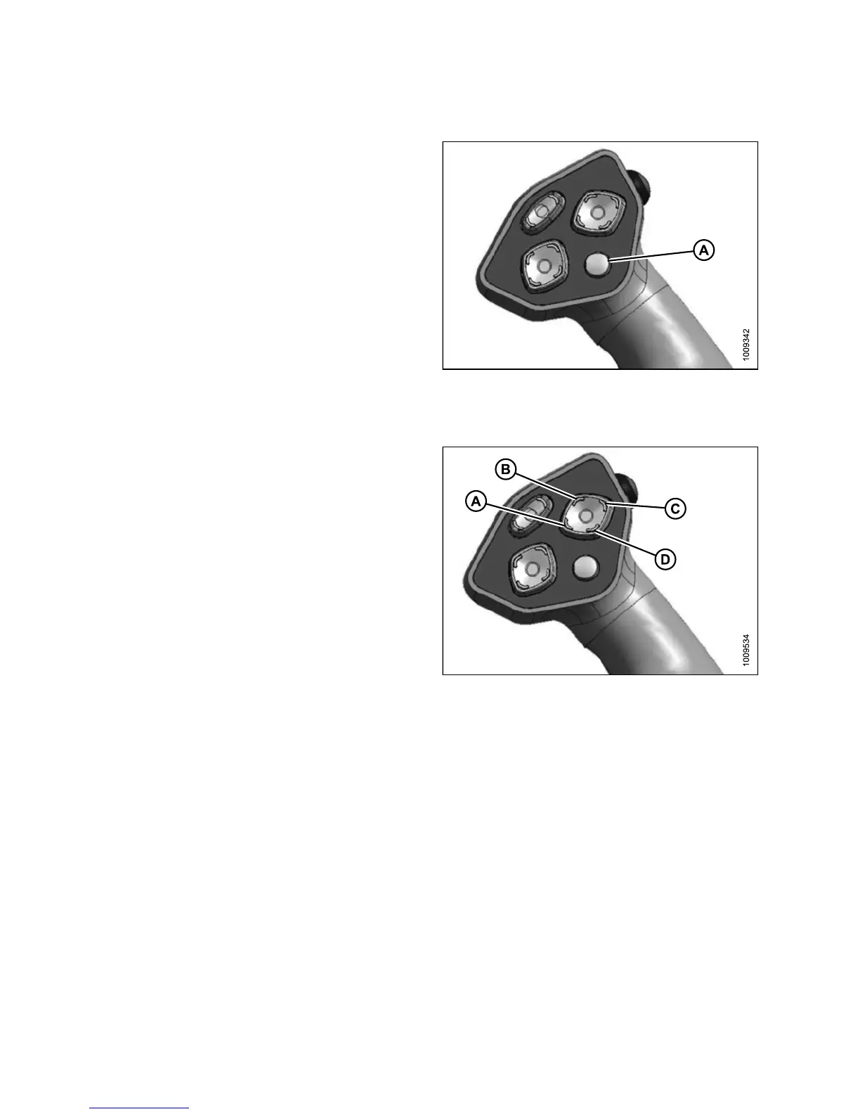
Pressing the display selector switch (A) selects and
displays th e settings on the cab display mo dule (CDM) top
line read-out for each of the header controls.
Press switch (A) to scroll through settings.
Figure 3.57: GSL
Reel Position Switches
The functions performed by the reel position switches
depend on which header is attached and the cab display
module (CDM) programming.
• For functions related to Double Windrow Attachment
(DWA) position, refer to:
– 4.4.10 Double Windrowing, page 211
• For functions related to Reel Fore-Aft position and height
on Draper headers, refer to:
– 4.6.4 A djusting the Reel Fore-Aft Position, page 281
– 4.6.5 Adjusting the Reel Height, page 282
• For the Center-Link Assist Cylinder, refer to the se ctio n
appropriate for your header:
– 4.5.3 Attaching an A-Series Header, page 237
– 4.5.1 Attaching a D-Series Header, page 213
– 4.5.5 Attaching an R-Series Header, page 257
NOTE
:
For d
etailed switch operating modes, refer to the section
in th
is manual, specific to your header.
Figure
3.58: Ground Speed Selector
A - Reel Down B - Reel Forward
C - Reel Up D - Reel Aft
147649 70 Revision A