OPERATION
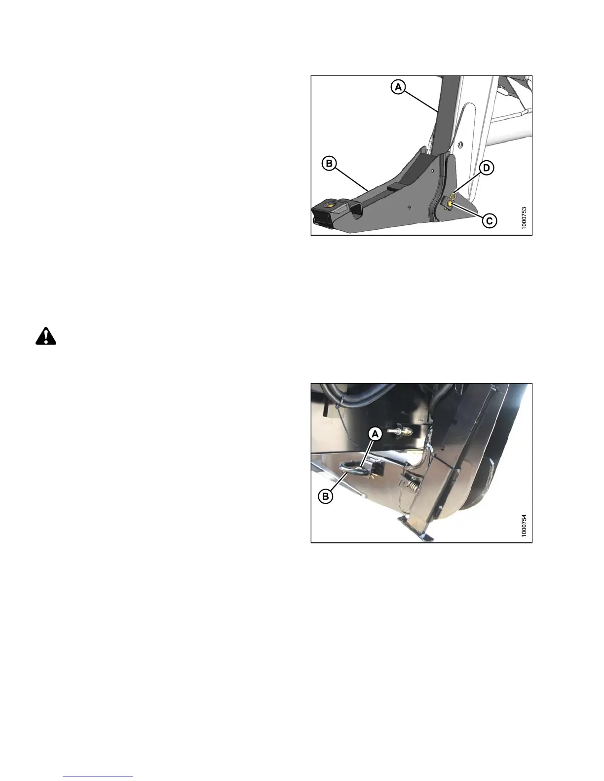
2. Position boot (B) onto lift linkage (A) and reinstall
pin (C). Pin ma y be installed from either side of boot.
3. Secure pin (C) with h airpin (D).
4. Repeat for opposite side.
Figure 4.110: Header Boot
Attaching a D-Series Header: Hyd raulic Center-Link with Optional Self-Alignment
NOTE:
Draper hea
der boots must be installed onto the windrower lift linkage before s tarting this procedure. Refer to
Attachin
g Header Boots, page 213.
DANGER
To avoid bodily injury or death from unexpected startup of the machine, always stop the engine and remove
the key from the ignition before leaving the operator’s seat for any reason.
1. Remove hairpin (A) from pins (B), and remove pins
from both header legs.
Figure 4.111: Header Leg
147649
2
14
Revision A