OPERATOR’S STATION
Cab-Forward, Engine Running, Hea der Engaged, Rotary Header Installed
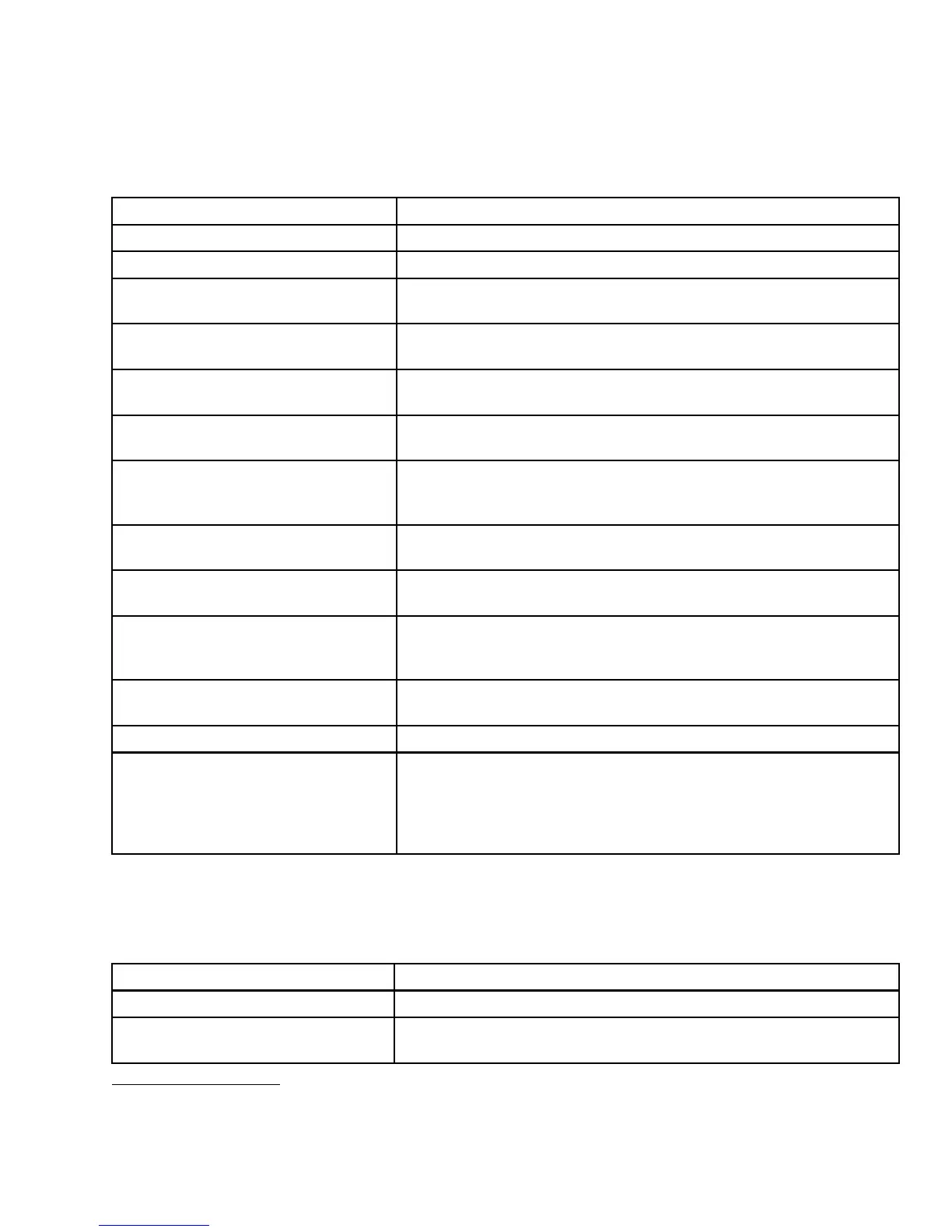
Scroll through display with cab display module (CDM) switch or gro un d speed lever (GS L) switch.
Display(LowerorUpperLine)
Description
#####.# ENGI
NE HRS Total engine operating time.
#####.# HEADER HRS
Total header operating time.
##.# ACRES/HOUR
##.# HE CTARES/HOUR (If Metric)
Actual cutting rate in acres (hectares)/hour.
###.# SUB A
CRES
###.# SUB H
ECTA RES (If Metric)
Area cut si
nce last reset. To reset, display SUB ACRES on lower line,
andholddo
wn program switch until display resets (5–7 seconds).
###### TOTAL ACRES
###### TOTAL HECT (If Metric)
Total area cut by machine.
#### DISC RPM
##.## DISC SENSOR
Disc rotational speed.
Sensor Disabled. RPM and SENSOR alternate at 1 second intervals.
##.# HE
ADER HEIGHT
##.# HE
IGHT SENSOR
Distan
ce setting (00.0–10.0) between cutterbar and ground.
Sensor
Disabled. HEIGHT and SENSOR alternate at 1 second
interv
als.
##.# HEADER ANGLE
##.# HEADER SENSOR
Angle setting (00.0–10.0) header relative to ground.
Sensor Disabled. ANGLE and SENSOR alternate at 1 second intervals.
##.# L FLOAT R ##.#
FLOAT SENS DIS ABLED
Left and right float setting (0.0–10.0).
Sensor Disabled.
LOAD
|■■■■||####
Bar graph representing hydraulic operating pressure. Full scale
is pre-programmed overload pressure (2500–5000 psi). If sensor
disabled, LOAD does not display
10
.
### °C or F HYD OIL TEMP
### °C or F HYD TEMP
Hydraulic oil temperature.
Sensor Disabled. TEMP and SENSOR alternate at 1 second intervals.
##
.# VOLTS Engine electrical system operating voltage.
SCROLL
SUB-MENU (Low er Line Only)
#### DISC RPM
##.# HEADER HEIGHT
LOAD|■■■■|■■■■| ####
Displays sub-menu after 2–3 seconds. Press SELECT to cancel.
Scroll throug h sub-menu display w ith CDM switch.
Miscellaneous Operational Information
Scroll through display with cab display module (CDM) switch or gro un d speed lever (GS L) switch.
Display (Upper Line) Description
HEADER DIS ENGAGED
Header drive is disengaged.
##.# FOOT DISK
AUGER or DRAPER w ill appear in place of D ISK, depending on type
of header attached.
10. The LOAD sensor to monitor knife/conditioner circuit pressure is optional-installed. To monitor reel/auger circuit
pressure, relocate sensor as per Form MD #169031, which is available through your Dealer.
147649 83 Revision A