OPERATOR’S STATION
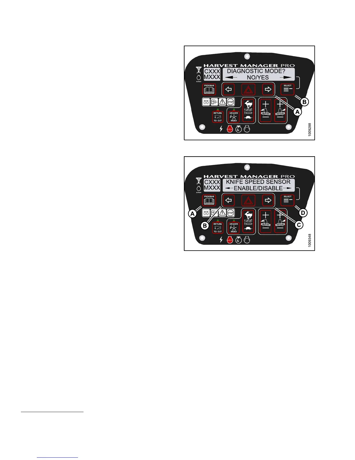
5. Press SELECT (B) until ENTER SENSOR SETUP ? is
displayed on the upper line.
• NO/YES is displayed on the lower line.
6. Press right (A) arrow to select Yes. Press SELECT (B).
• KNIFE SPEED SENSOR is displayed on the
lower line .
• ENABLE/DISABLE is displayed on the lower line.
Figure 3.16
3: M155 Diagnostic Functions
7. Press left (B) arrow to enable a sensor. Press right (C)
arrow to disable sensor. Press SELECT (D) to confirm
selection and move on to next sensor.
The following sensors are available:
•HEADERHT
SENSOR
•HEADERTI
LT SENSOR
• KNIFE SPE
ED SE NSOR
• REEL SPEE
D SENSOR
•HEADERF
LOAT SENSOR
• OVERLOA
D PRES S URE
15
•HYDOILT
EMP S ENSOR
When se
nsors have been modified, press SELECT (D)
to disp
lay t he EXIT SE NSOR SETUP? selection.
Figure 3.164: M155 Header Senors
8. Press right arrow to select YES. Press SELECT.
9. Press PROGRAM to exit Programming Mode or press
SELECT to proceed to next DIAGN OSTIC MODE.
Displaying Header S
ensors Input Signals
You can display individual sensor input signals in the event of a malfunction or as part of a troubleshooting routine.
NOTE:
The header MUST be attached to the windrower to perform this procedure. The cab display module (CDM)
automatically adjusts its programming for each header. For m ore information, refer to 4.5Attachingand
Detaching Headers, page 213.
15. Requires installation of optional pressure sensor (MD #5574).
147649 132 Revision A