MAINTENANCE AND SERVICING
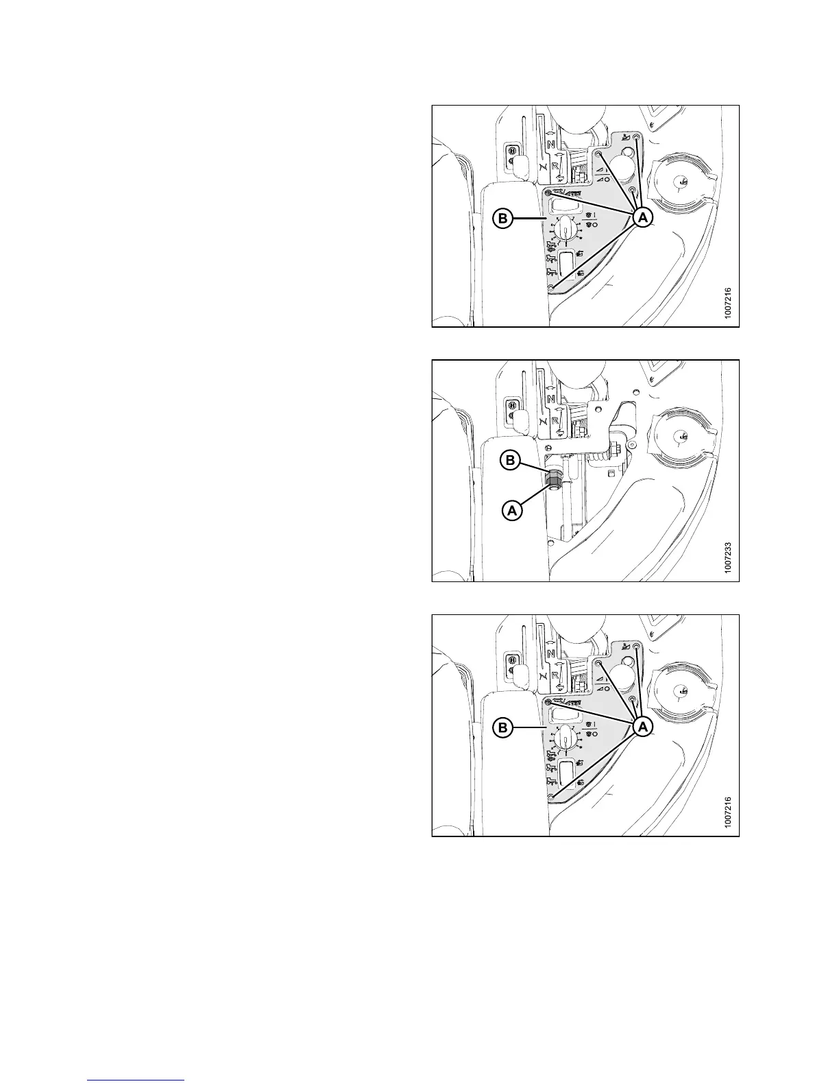
1. Remove the five screw s (A) securing control panel (B)
to console, remove panel, and store in the tray.
Figure 5.16: Header Control Panel
2. Back off the jam nut (A) and turn nut (B) to either tighten
or loosen the pivot. The nut should be tightened to
snug and then backed off 1/2 turn.
3. Tighten jam nut (A).
4. Check movement of GSL.
Figure 5.17: Header Control Panel
5. Reinstall the control panel (B) with the five screws (A).
Figure 5.18: Header Control Panel
Adjusting Ground Speed Lever (GSL) F ore-Aft Movement
The
GSL should remain as positioned by the Operator yet be movable without excessive force.
Adj
ust as follows:
147649 318 Revision A