OPERATOR’S STATION
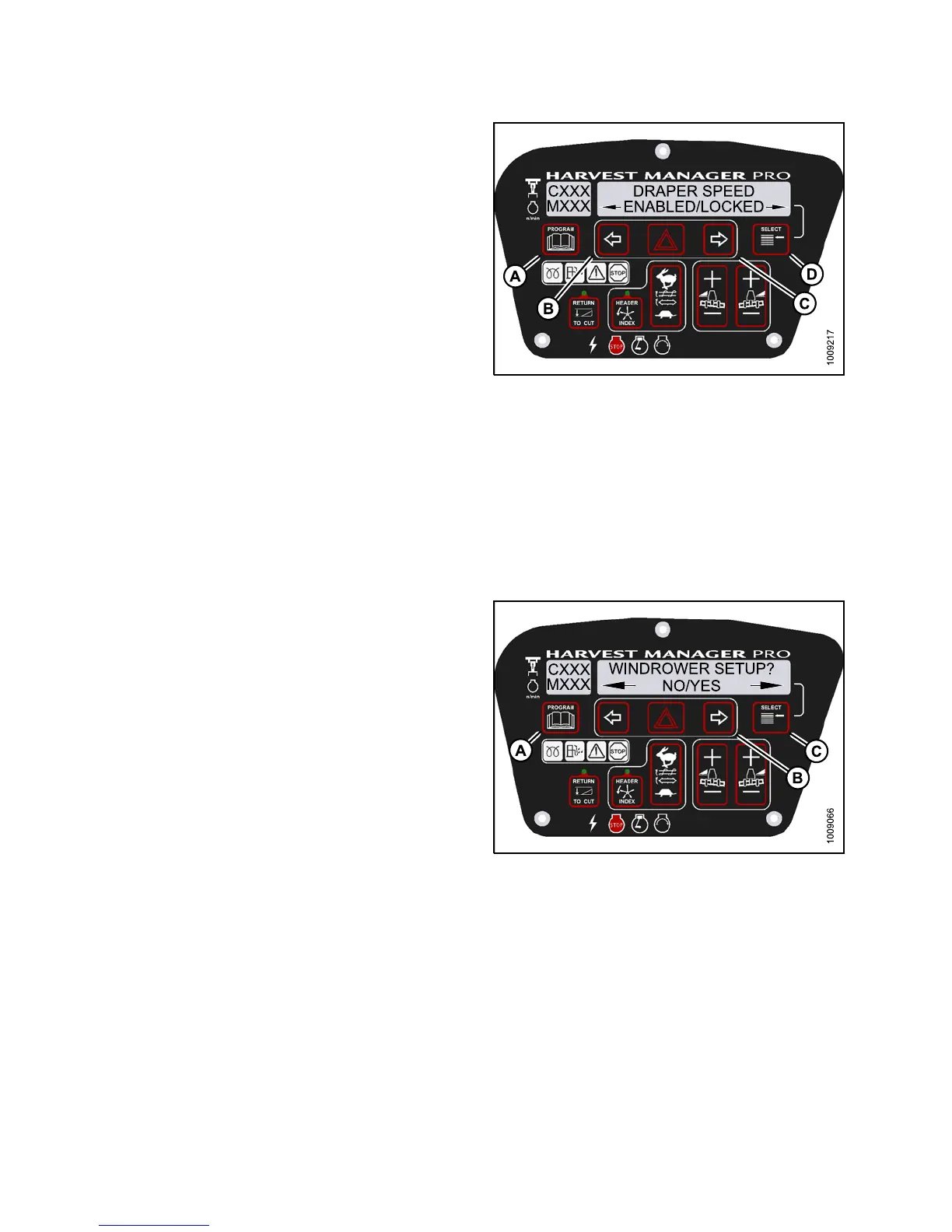
6. Press SELECT (D) until DRAPER SPEED is displayed
on the upper line.
• ENABLED/L O C KED is displayed on the lower line.
7. Press left arrow (B) to enable DRAPER SPEED control
switch, or press right arrow (C) to lock DRAPER
SPEED control switch.
8. Press PROGRAM (A) to exit Programming Mode or
press SELECT (D ) to proceed to next WINDROWER
SETUP action.
Figure 3.14
2: M155 Draper Control Lock
Activatin
g the Auger Speed Control Lock Out
NOTE:
• This procedure is for A40-D Headers only.
• An auger header MUST be attached to the w indrower to perform this procedure. The cab display module
(CDM) automatically adjusts its programming for each header. For more information, refer to 4.5 Attaching
and Detaching Headers, page 213.
1. Turn ignition key to RUN, or start the engine.
2. Press PROGRAM (A) and SELECT (C) on cab display
module (CDM) to enter Programming Mode.
• WINDROWER SETUP? is displayed on the
upper line.
• NO/YES is displayed on the lower line.
3. Press right (B) arrow to select YES. Press SELECT (C).
• SET KNIFE SPEED? is displayed on the upper line.
Figu
re 3.143: M155 CDM Programming Buttons
147649
1
22
Revision A