OPERATOR’S STATION
Calibrating the Header Tilt Sensor
NOTE:
• The header MUST be attach ed to the windrower to perform this proce du re. The cab display module (CDM)
automatically adjusts its programming for each header. Refer to 4.5 Attaching and Detaching Headers, page
213.
• This procedure requires installation of the optional Hydraulic Center-Link (MD #B4650) .
• The engine MUST be running to perform this procedure.
1. Turn ign iti
on key to RUN, or start the engine.
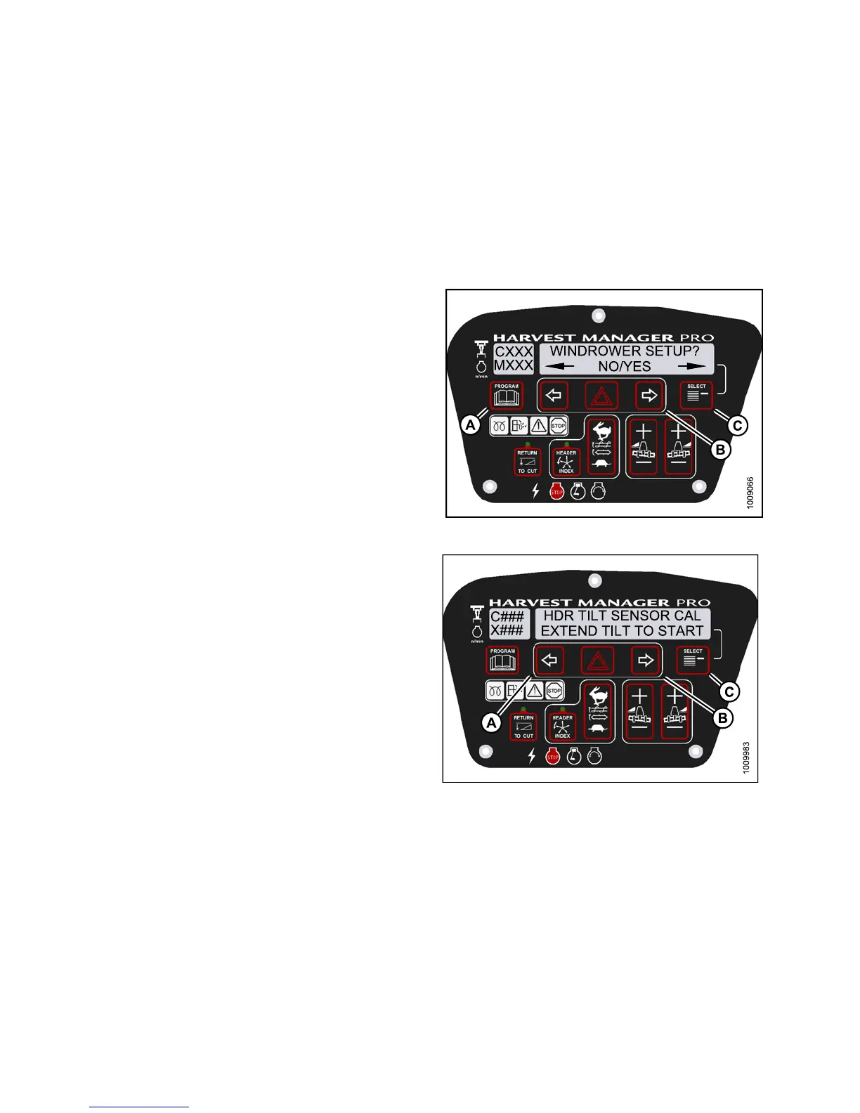
2. Press PROGR
AM (A) and SELECT (C) on cab display
module (CDM
) t o enter Programmin g Mode.
• WINDROWER
SETUP? is displayed on the
upper line
.
3. Press SELE
CT (C) until CALIBRATE SENSORS? is
displayed
on the upper line.
•NO/YESis
displayed on the lower line.
Figure 3.89: M155 CDM Programming Buttons
4. Press ri
ght (B) arro w to select Yes. Press SELECT (C).
•TOCALIB
RAT E SE LECT is displayed in upper line
5. Press l
eft (A) or right (B) arrow until HEAD ER TILT is
displa
yed on the lower line. Press SELECT (C).
•HDRTIL
T SENSOR CAL is displayed on the
upper l
ine.
• EXTEN
D TILT TO START is disp la ye d on the
lower
line.
Figure 3.90: M155 Header Tilt
147649 98 Revision A