OPERATOR’S STATION
CAUTION
Check to be sure all bystanders have cleared the area.
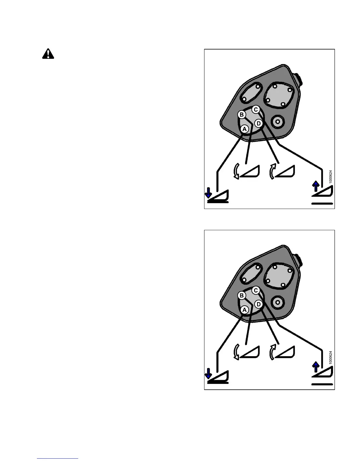
6. Press and hold the HEADER U P (C) button on the
ground speed lever (GSL).
• CALIBRATING HEIGHT is displayed on the
upper line.
• RAISE HEADER H OLD is displayed on the
lower lin e.
NOTE:
ThewordHOLDwillflash during calibration.
RAISE HEADER DONE will display on the lower
line once calibratio n is complete.
7. Release the HEADER UP (C) button.
• HEIGHT SENSOR CAL is displayed on the
upper line.
• PRESS LOWER HEADER is displayed on the
lower lin e.
Figure 3.87: Header Height Controls on Ground
Speed Lever
8. Press and hold HEADER DOWN (A) button on GSL.
NOTE:
ThewordHOLDwillflash during calibration. HT
SENSOR COMPLETE will display on the low er
line once calibratio n is complete.
9. Release HEADER DO W N (A) button.
• TO CALIBRATE SELEC T is displayed on the
upper line.
• HEADER HEIGHT is displayed on the lower line.
10. Press right arrow to select next header sensor
calibration or S TOP & EXIT. Press SELECT.
Refer to Calibrating the Header Tilt Sensor, page 98 or
Calibrating the Header Float Sensors, page 100.
11. Press PROGRAM to exit Programming Mode.
Fi
gure 3.88: Header Height Controls on Ground
Sp
eed Lever
147649 97 Revision A