OPERATOR’S STATION
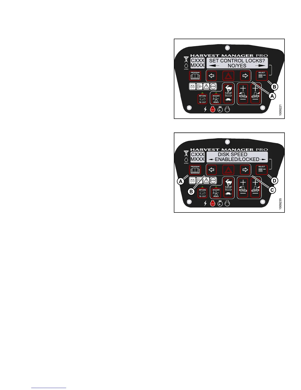
4. Press SELECT (B) until SET CONTROL LOCK S? is
displayed on the upper line.
• NO/YES is displayed on the lower line .
5. Press right (A) arrow to select YES. Press SELECT (B).
Figure 3.13
5: M155 Control Locks
6. Press SELECT (D) until DISK SPEED is displayed on
the upper line.
• ENABLED/LOC KED is displayed on the lower line.
7. Press left arrow (B) to enable DISK SPEED control
switch, or press right arrow (C) to lock DISK SPEED
control switch.
8. Press P ROGRAM (A ) to exit Prog r am ming Mode or
press SELECT (D) to proceed to next WINDROWER
SETUP action.
Figure 3.136: M155 Disc Speed Control Lock
Activating the H eader Float Control Lock Out
NOTE:
The header MUST be attached to the windrower to perform this procedure. The cab display m odule (CDM)
automatically adjusts its programming for each header. For more information, refer to 4.5 Attaching and
Detaching Headers, page 213.
147649 119 Revision A