OPERATION
4. Adjust the header angle with the HEADER TILT UP (E)orHEADERTILTDOWN(F)switchesontheGSL.The
CDM displays between 00.0 and 10.0. This step is not required when height only has been preselected.
5. Press the RETURN TO CUT switch (A) on th e CDM . The indica to r light will illuminate a nd the settings are now
programmed into the windrower control module (WCM).
Using the Return to Cut Feature
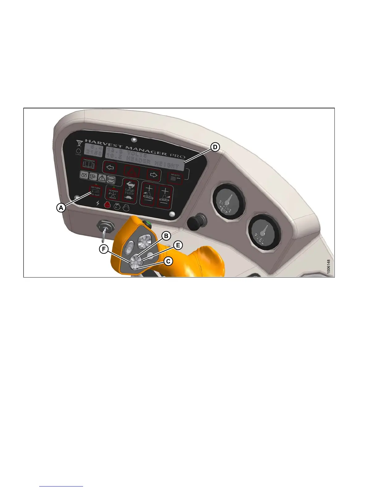
Figure 4.99: Operator Console
A - Return to Cut
B - Head
er Up
C - Header Down
D - Display E - Header Tilt Up F - Header Tilt Do wn
Use the RETURN TO CUT feature as follows:
IMPORTANT:
Ensure the header is eng a ged and the RETURN TO CUT switch (A) is illuminated.
NOTE:
The header can be raised or lowered by pressing and holding the HEADER UP (B) or H EADE R D OW N (C)
switches on the ground speed lever (GSL).
1. If header is above the preset cutting height, momentarily press HEADER DOWN switch (C) and the header
will return to preset height.
2. If the header is below the preset height, press and hold the HEADER UP (B) switch to raise the header. Release
switch to stop header. Alarm will sound when header rises past the preset height.
3. If the header angle changes, double-click (two clicks within 0.5 seconds) the HEADER TILT UP (E) or HEADER
TILT DOWN switch (F) and th e header will return to the preset angle.
147649 208 Revision A