OPERATION
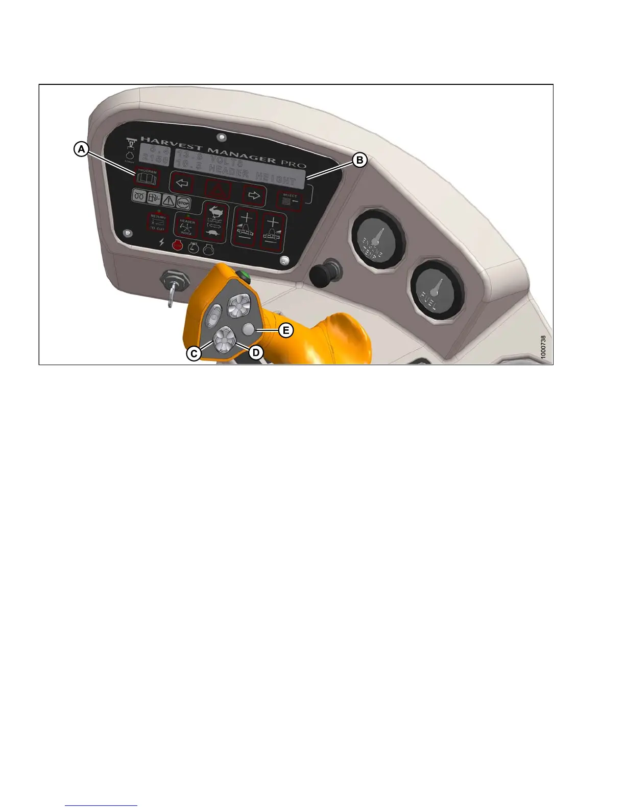
Figure 4.92: Operator Console
A - Progra
mButton
B-Displa
y
C - Header Tilt Down
D - Header Tilt Up
E - Display Selector
Hydraulic Link (Optional)
Adjust the header angle as follows:
•Todecrease(flatten) header angle, operate HEADER TILT UP switch (D) on ground speed lever (GSL) handle
so that cylinder retracts. The CDM display will show a reading on the lower line of decreasing value between
00.0 and 10.0.
• To increase (steepen) header angle, operate HEADER TILT DOWN switch (C) on GSL handle so the cylinder
extends. The CDM display will show a reading on the lower line of increasing value between 00.0 and 10.0.
NOTE:
The HEA
DER TILT switch can be locked out to prevent inadvertent header angle changes when pressing the
HEADER
HEIGHT control switches. Refer to Activating the Header Tilt Control Lock Out, page 126.
147649 204 Revision A