OPERATION
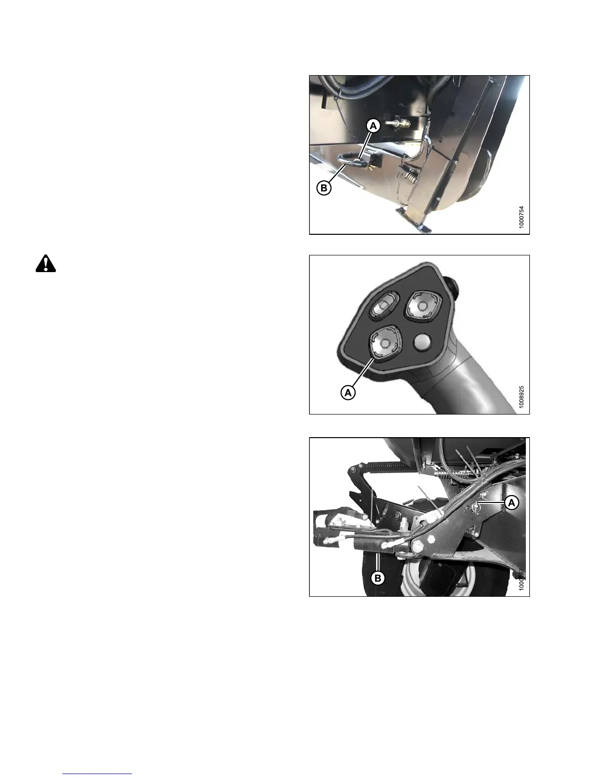
1. Remove hairpin (A) from pins (B), and remove pins
from both header legs.
Figure 4.125: Header Leg
CAUTION
Check to be sure a ll bystanders have cleared the area.
IMPORTANT:
Remove protective cover from exhaust stack prior to
starting engine.
2. Start the engine and activate the header down
button (A) on the ground speed lever (GSL) to fully
retract header lift cylinders.
Figure 4.126: GSL
3. Reloca
te pin (A) in frame linkage as required to
raise t
he center-link (B) until the hook is above the
attach
ment pin on the header.
IMPOR
TANT:
If the
center-link is too low, it may contact the
heade
r as the windrower approaches the header
for ho
okup.
Figure 4.127: Hydraulic Center-Link without
Self-Alignm e nt K it
147649 220 Revision A