OPERATION
3. Relocate pin (A) in frame linkage as required to
raise the center-link (B) until the hook is above the
attachment pin on the header.
IMPORTANT:
If the center-link is too low, it may contact the
header as the windrower approaches the header
for hookup.
Figure 4.175: Hydraulic Center-Link without
Self-Alignm e nt K it
4. Drive the windrower slowly forward until the windrower
feet (A) enter the header boots (B). Continue driving
slowly forward until the feet engage the boots and the
header nudges forward.
Figure 4.176: Header Boot
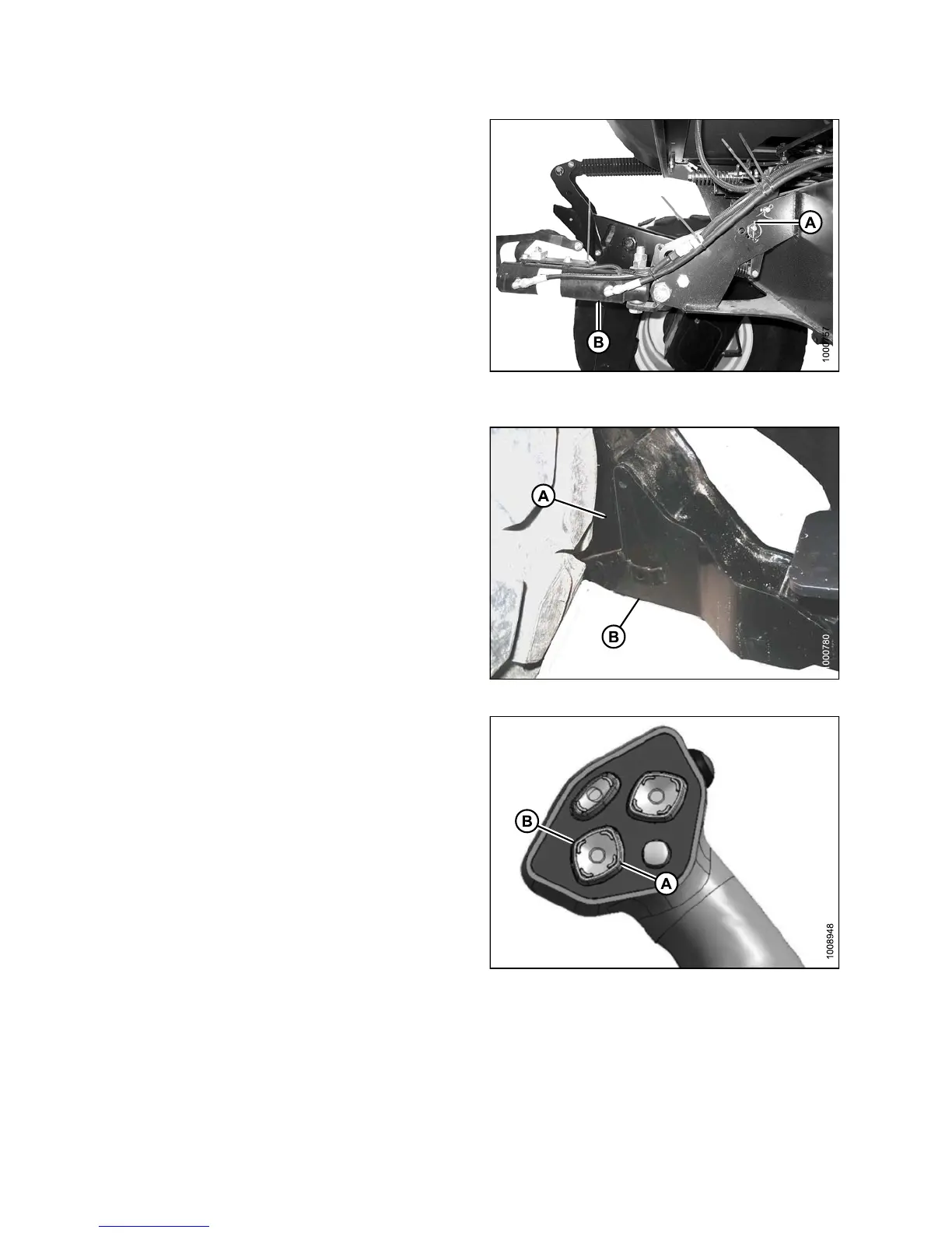
5. Use the following GSL func tions to position the
center-link hook above the header attachment pin:
• Header tilt up (A) to retract center-link
• Header tilt down (B) to extend center-link
6. Stop engine and remove key from ignition.
Figure 4.177: GSL
147649 240 Revision A